LED side marker headache

Bill W

New Member
Joined
Apr 26, 2020
Messages
7
Location
Levittown Pennsylvania
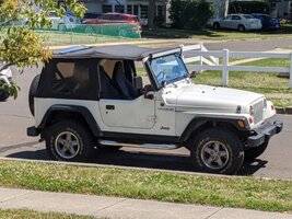
OK, so I started replacing all of my bulbs with leds. Of course now the side markers don't work. After reading up on it there is a mod of the wire with a resistor and diode. Maybe I'm getting lazy inmy old age. Does anybody know of the availability of one that is pre-made, or an adapter type harness?

IMG_20200614_140128.jpg


IMG_20200614_140128.jpg
 
Would it be terrible to just have incandescent front turn signals? Memory is fuzzy but if I remember correctly the side markers ground through the front facing turn signals, so led turns make the side markers not work, but you can use led markers.
 
  • Like
Reactions: Vtx531
Or for that matter, would it be terrible if they just flashed together instead of alternating? Shooting from the hip and without doing any research, perhaps that would be easier?
 
Would it be terrible to just have incandescent front turn signals? Memory is fuzzy but if I remember correctly the side markers ground through the front facing turn signals, so led turns make the side markers not work, but you can use led markers.

i was just trying to update. I didn't realize it was this involved, it only takes a couple of minutes to change bulbs (nice and quick I thought), Hmm... now I have to update the flasher, oh, these amazon cheapie ep27's don't work (three differnt brands, turn circuit good, flashers no just a loud buzz), but evenetually gotr the Diode Dynamics brand LM-470 that did the trick after taking the cover off for the fourth time. Now to make the side makers work I need to cut the side marker harness and add 2 diodes and a resistor to each side.
I just thought bulb to led replacement should be easier.
 
What a lot of people don't understand is that an incandescent bulb is a voltage device whilst an light emitting diode (LED) is a current device. Get the correct voltage across the bulb and it lights up; easy peasy. To make the LED work, you must install it into a circuit that provides the correct current (in my day, about 100 mA) to make it light. The old style blinkers make things more confusing. Many of them were made of bimetallic strips. One metal heated up quicker than the other, causing the strip to bend away from the contact. Once cooled, it bent back, so you got blinking action. So, while the bulbs were voltage devices, the blinker was a current device. That's why it blinked faster when you hooked up the trailer, more lights - more load - higher current.
Most adapters use a resistor to manage the correct current in the LED circuit, using Georg Ohm's law: Voltage is equal to Current times Resistance or E=IR. So, a 12V source and a desired current of 100mA and E/I=R means 12/.1=
 
Side marker lights work by voltage passing thru them. This is nothing new. This was the same problem on all the 70s 80s 90s GM cars and trucks. When the headlights are off, the side marker light is passed thru the ground for the turn signal. So when you turn the turn signal on it flashes with the front signal. When the headlights are on, its reversed which causes the side marker to stay on with the parking light but alternate with the turn signal. This reverses the polarity in the side marker light. Reversing the polarity is not something you can do with an LED. Its a diode, the polarity only works one way.

Super bright LEDS sells LEDs that will work in this situation in GM cars and trucks i have worked on. I have been doing LED bulbs for 20 years.
The Jeep TJs however, at least mine and my buddys 2000 will NOT work correctly even with the correct bulbs installed. They will light, but even with the LED flasher there will be flashing issues. The only way i have found to solve any of these problems is continue to run regular bulbs in the front turn signal/parking lights and leave LEDs for the side markers or vice versa.

There MUST be a load on the front turn signal circuit or there will be problems.
 
  • Like
Reactions: psrivats
This subject is full of misinformation. The problem happens when LEDs are installed into the FRONT sockets. The LEDs being in the front breaks the side marker’s ability to reach ground. The solution is to rewire the side markers, a 2-wire 1-stage brightness/filament bulb to be 2 stages of brightness: resisted/dimmed brightness for a parking lamp and full brightness for a turn signal.

The problem isn’t that you need an led flasher, need more current on the circuit, or anything else. You will need an LED flasher for the proper flash rate but that is NOT why the side marker issue exists. The side marker issue exists solely because the side markers rely on the front and putting LEDs up front screws it up.

I can make you some harnesses if you want to send me some parts like bulb socket sets and male 194 socket adapters. You will end up with excess slack that you’ll need to secure and you’ll need to run a wire with a ring terminal on it to A ground bolt at the headlight or similar.
 
Or for that matter, would it be terrible if they just flashed together instead of alternating? Shooting from the hip and without doing any research, perhaps that would be easier?

Alternating and flashing together is a function of the way they are wired at the factory. For an incandescent bulb to both be a parking lamp and a turn signal, it has to alternate when the headlights are on and the turn signal is used. No way around it. During the day it will blink with the front signal. If you wanted them to blink together all the time then you’d have to get rid of the parking lamp function which is not legal for a front side marker. Doubt Florida cares, but not having a front side marker at night would be less than ideal.
 
Side marker lights work by voltage passing thru them. This is nothing new. This was the same problem on all the 70s 80s 90s GM cars and trucks. When the headlights are off, the side marker light is passed thru the ground for the turn signal. So when you turn the turn signal on it flashes with the front signal. When the headlights are on, its reversed which causes the side marker to stay on with the parking light but alternate with the turn signal. This reverses the polarity in the side marker light. Reversing the polarity is not something you can do with an LED. Its a diode, the polarity only works one way.

Super bright LEDS sells LEDs that will work in this situation in GM cars and trucks i have worked on. I have been doing LED bulbs for 20 years.
The Jeep TJs however, at least mine and my buddys 2000 will NOT work correctly even with the correct bulbs installed. They will light, but even with the LED flasher there will be flashing issues. The only way i have found to solve any of these problems is continue to run regular bulbs in the front turn signal/parking lights and leave LEDs for the side markers or vice versa.

There MUST be a load on the front turn signal circuit or there will be problems.
The solution is the diode/resistor mod the OP mentioned. You rewire the side markers to be independent of the front bulbs and have no more problems. The only reason for this thread is he doesn’t feel like doing the diode resistor mod and wants to purchase that from elsewhere.
 
The big part of all the confusion is the word resistor. As soon as folks see that word, they think you’re talking about load and tricking the turn signal circuit into blinking. No, there are two types of resistors: inline and load.

Inline resistors are tiny and are to be used “inline” on a wire. They waste current and effectively dim the LED downstream. That is the resistor type needed for the diode/resistor harness that fixes the side markers.

The other resistor type is the load resistor, which can be used to pull load on a circuit and trick a turn signal flasher into working with a low amperage LED gets installed in place of a high amperage incandescent filament bulb. The LEDs draw practically nothing, so a load resistor is wired into the circuit and used to pull load that the old incandescent pulled itself. Or, you can use an LED flasher instead of wiring in load resistors.
 
  • Like
Reactions: Zorba
OK, here's the update
I got two replacement sockets which actually have an eye on the end of one wire, two T10 male pigtales some diodes and resistors. I soldered them all together making an adapter harness and leaving the original alone. . Next was to run the wire with the eye connector to a grounfOf course when I plugged it in the turn funtion worked, nut not the park. I decided to try the other side and it worked fine. Went into it a little further and found an open in splice s142. repaired that and now they all work fine!
 
  • Like
Reactions: machoheadgames