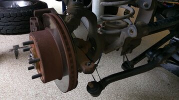
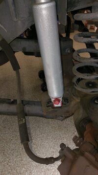
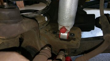
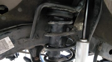
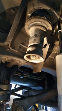
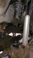
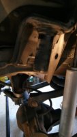
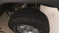
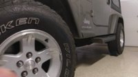
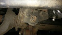
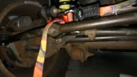
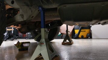
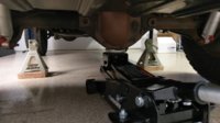
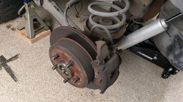
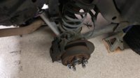
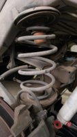
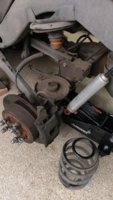
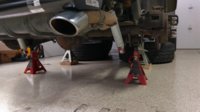
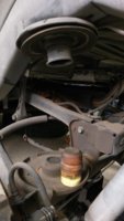
Stock Spring Swap Walk-Thru with Pics

fuse

TJ Enthusiast
Supporting Member
Joined
Jun 5, 2018
Messages
706
Location
San Diego, CA
When I bought my 05 Sport, it had some deferred maintenance issues that the PO had ignored. One issue is that the ride was harsh and jittery, nothing like you'd expect from the relatively new RS9000X shocks the PO had installed.

With some help from some really knowledgeable people on this forum, I figured that my stock springs were sagging after some 125K miles. I decided to go ahead and swap them for some Moog springs to restore the Jeep to stock height.

Although I've wrenched on other things before, this was my first major job on the Jeep. I took lots of pics and documented everything while figuring out the sagging springs, so I figured I would do that for the spring swap too.

I started out reading the factory service manual. Then I read a bunch of install instructions for lift kits, especially instructions from Teraflex which have great line drawings. And I watched a bunch of YouTube videos of idiots doing really stupid things to their Jeeps — great source of information about what NOT to do! But, the videos really helped me see how the suspension moves when you disassemble things before actually trying it on my Jeep.

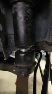
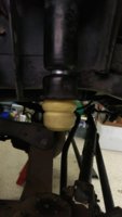
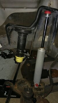
While I had the springs out, I figured I would do the bump stop check too. I'm running 31x10.5R15 tires on stock wheels and suspension. That supposedly fits, but as I found out, I do have some clearance issues. I'll post all that in a separate thread.

There are a lot of little steps with lots of pics, so I'll have four more posts after this one: front spring removal, front spring install, rear spring removal, and rear spring install.

Also, all this info is for stock springs on a Jeep at stock height. If I were installing a lift kit, I'd probably have to do more to get the springs in place, and depending on the kit I'd probably have to install a bunch more stuff too. But hopefully this stuff is helpful anyway to cover the basics if you're doing something similar.
 
Front Spring Removal

I've included the tools and torque spec for each fastener in parens, even for disassembly where it's nice to know how hard you should have to push on a bolt to get it loose. These specs are for my 05 Sport. I don't know if other models or years might have different fasteners or specs, so check yours before you start wrenching.

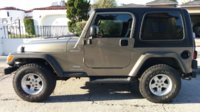
1. Place the vehicle on a level surface with the transmission in park (or in gear for a MT), the transfer case in 2H and the parking brake set.
IMAG0692.jpg

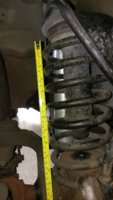
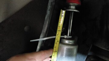
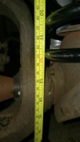
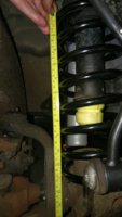
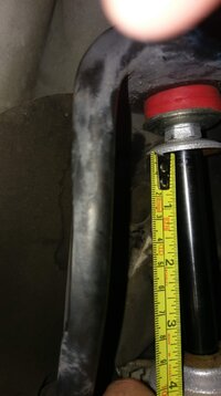
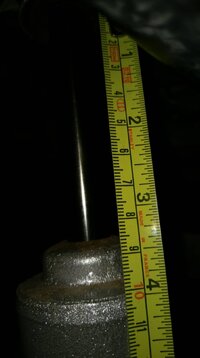
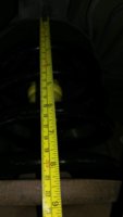
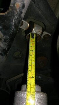
2. Measure the front spring height and shock position.
IMAG0700.jpg IMAG0697.jpg

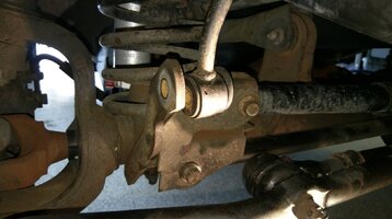
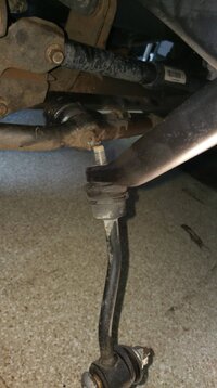
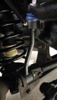
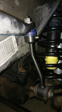
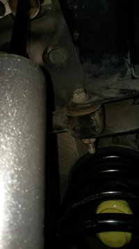
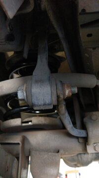
3. Disconnect sway bar links at axle. (18mm & T55, 75 ft-lbs.) — FSM says to do this after jacking up and supporting the vehicle, but I found that the bolts are under load if you do that and it's hard to get them out. If you do this while the vehicle is sitting on level ground, there should be little to no tension on the bolts. I had to lift up slightly on bumper to slide the bolt out, but then my Jeep was sitting a little low.
IMAG0702.jpg IMAG0701.jpg

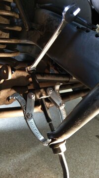
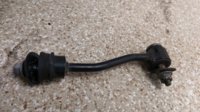
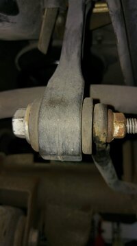
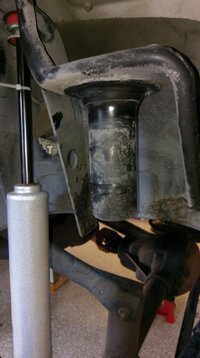
4. Disconnect sway bar links at sway bar and remove old links. Use a puller tool to separate links from sway bar. (15mm, 45 ft-lbs.) — You don't have to do this if you're just swapping springs, but my links were shot so I replaced them while I was working on the springs.
IMAG0704.jpg IMAG0705.jpg IMAG0706.jpg

5. Remove the track bar from the axle bracket. Loosely tie the track bar to the bracket in a position clear of other components. (15mm, 40 ft-lbs.) — This is another step that FSM says to do after you've jacked up and supported the vehicle, but the bolt will certainly be under load if you do that. Getting this bolt out while it's under load is a PITA and you risk damaging the threads. If you take out this bolt while the vehicle is sitting on level ground, there should be little to no tension on the bolt. If you do need to release tension on the bolt to slide it out, have a friend do a little dry steering to gently shift the position of the frame relative to the axle.
IMAG0707.jpg

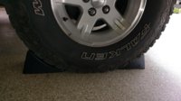
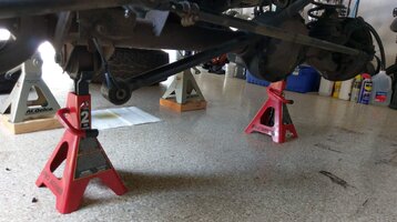
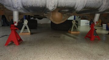
6. Chock the rear wheels. Raise and support the vehicle.
IMAG0709.jpg IMAG0710.jpg

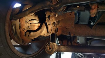
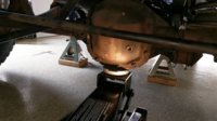
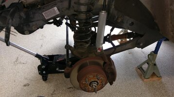
7. Position a hydraulic jack under the axle to support it.
IMAG0712.jpg

8. Remove the front wheels. (Tire iron, 100 ft-lbs.)
IMAG0714.jpg

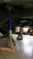
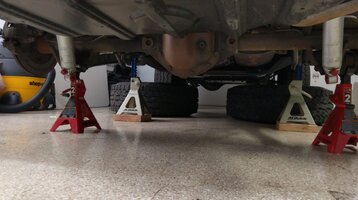
9. Support the axle with jack stands.
IMAG0745.jpg

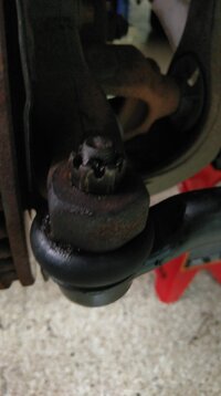
10. Remove the right side of the drag link from the right-side knuckle (19mm, 55 ft lbs.):
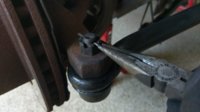
· Remove the cotter pin and nut at the steering knuckle.
IMAG0750.jpg
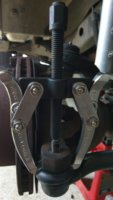
· Remove the drag link from the steering knuckle with a puller tool. — It helps if you steer to the left first, because this opens up a better position for the puller tool.
IMAG0751.jpg
· Loosely tie the drag link to the knuckle in a position clear of other components.
IMAG0716.jpg

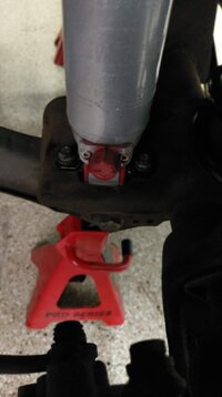
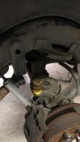
11. Unmount the front shocks from the axle. (13mm long & 10mm box end, 21 ft-lbs~250 in-lbs.) — Technically you only need a short 13mm socket, but I had trouble getting my wrench into position with a short socket. A long socket or a socket extension helps.
IMAG0717.jpg IMAG0718.jpg

12. Lower the left side of the axle until the spring is free from the upper mount, or until the lower suspension arm contacts the axle bracket. — I was able to free the spring without interference from the lower suspension arm, but you might have trouble if you have a lift kit.
IMAG0752.jpg IMAG0720.jpg

13. If necessary, remove left lower suspension arm mounting nuts and bolts from the frame. (21mm & 21mm box end, 130 ft-lbs.) — FSM says you need to do this even for stock springs, but I was able to get the spring out without touching these bolts.
IMAG0753.jpg

14. If necessary, lower the left side of the axle further until the spring is free from the upper mount. — I didn't need to do this because my springs were already free.

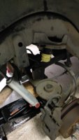
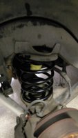
15. If necessary, remove the left coil spring retainer clip. (13mm, 16 ft-lbs.) Remove the left coil spring. NOTE: Rotation of the spring and prying down slightly on the axle will aid in removal. — My Jeep doesn't have a spring retainer clip. You can yank on the spring to slightly compress it while putting a foot on the hub to push the axle down.
IMAG0721.jpg

16. Return the left side of the axle to the starting position and support with jack stands.
IMAG0728.jpg

17. Pull the left jounce bumper out of the bump stop cup. — Not necessary if you're just swapping springs, but I replaced all the rubber components too.
IMAG0726.jpg

18. Remove the bump stop cup. (15mm, ?? ft-lbs.) — I couldn't find a torque spec for this bolt. It's not in too tight, though.
IMAG0754.jpg

19. Remove the left upper spring isolator. Use a screwdriver to pry the isolator free. — Not necessary unless you're going to replace it as I did.
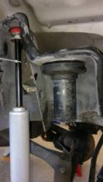
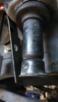
IMAG0727.jpg

20. Install the new spring isolator in the top spring mount and seat it fully in the spring mount. — Again, only necessary if you're replacing it.
IMAG0756.jpg

21. Reinstall the bump stop cup. (15mm, ?? ft-lbs.) — I couldn't find a torque spec for this bolt, so I just tightened it up about as much as it was when I found it.
IMAG0758.jpg

22. If necessary, reinstall the left lower suspension arm mounting nut and bolt and hand tighten. (21mm & 21mm box end, hand tight.) — I didn't remove this bolt.

23. Lower the right side of the axle until the spring is free from the upper mount, or until the lower suspension arm contacts the axle bracket.— I was able to free the spring without interference from the lower suspension arm, but you might have trouble if you have a lift kit.
IMAG0729.jpg

24. If necessary, remove right lower suspension arm mounting nuts and bolts from the frame. (21mm & 21mm box end, 130 ft-lbs.) — The spring was already free, so I didn't have to do this.

25. If necessary, lower the right side of the axle further until the spring is free from the upper mount. — I didn't have to do this, but you might have to if you have a lift kit.

26. Remove the right coil spring retainer clip (13mm, 16 ft-lbs.) and remove the spring. Rotation of the spring and prying down slightly on the axle will aid in removal. — My Jeep doesn't have a spring retainer clip. Pulling out the right spring is easier than the left spring. I just slid it right out.
IMAG0730.jpg

27. Return the right side of the axle to the starting position and support with jack stands.
IMAG0766.jpg

28. Pull the right jounce bumper out of the bump stop cup. — Only if you plan to replace it.
IMAG0761.jpg

29. Remove the bump stop cup. (15mm, ?? ft-lbs.) — I couldn't find a torque spec for this bolt.
IMAG0731.jpg

30. Remove the right upper spring isolator. Use a screwdriver to pry the isolator free. — Only if you plan to replace the isolator.
IMAG0732.jpg

31. Install the new spring isolator in the top spring mount and seat it fully in the spring mount.
IMAG0733.jpg

32. Reinstall the bump stop cup. (15mm, ?? ft-lbs.) — I couldn't find a torque spec for this bolt so I just tightened it about as much as it was when I found it.
IMAG0764.jpg

33. If necessary, reinstall the right lower suspension arm mounting nuts and bolts and hand tighten. (21mm & 21mm box end, hand tight.) — I didn't have to remove this bolt.

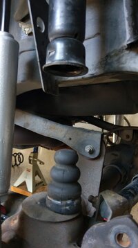
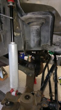
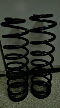
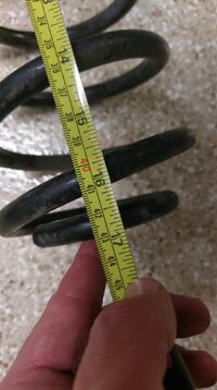
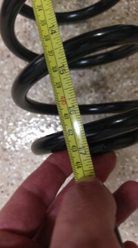
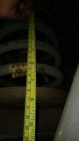
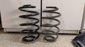
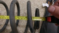
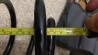
34. Measure the old spring lengths and the new spring lengths. — The moment of truth. The old springs were a little more than 1/4" shorter than the new springs.
IMAG0851.jpg IMAG0854.jpg IMAG0856.jpg
 
Last edited:
Front Spring Install

1. If necessary, install bump stop extensions. After messing around with bump stop checks for a bit, I decided that I only needed about 5mm to keep my tires from hitting the fender and to keep my shocks from being fully compressed. That's a tiny adjustment, so I used a couple M10 fender washers to extend the bump stop cups. (15mm, ?? ft-lbs.)
IMAG0862.jpg

2. Install the new jounce bumpers in the bump stop cups.
IMAG0865.jpg

3. Lower the left side of the axle until there is room to install the new spring, or until the lower suspension arm contacts the axle bracket. — I had just enough room for the new spring with a gap left at the axle bracket.
IMAG0866.jpg IMAG0869.jpg

4. If necessary, remove left lower suspension arm mounting nuts and bolts from the frame. (21mm & 21mm box end, 130 ft-lbs.) — I didn't have to do this.

5. If necessary, lower the left side of the axle further until there is room to install the new spring. — I didn't have to do this.

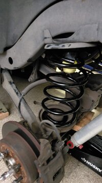
6. Install the new left side spring. Rotate the spring so it fits the slot on the axle pad. NOTE: Prying down slightly on the axle will aid in install. — I had just enough room to install the new spring by pushing down on the hub with my foot and using both hands to pull up on the spring to compress it a little.
IMAG0870.jpg

7. Install and tighten the left spring retainer clip. (13mm, 16 ft-lbs.) — My Jeep doesn't have a spring retainer clip.

8. If necessary, reinstall the left lower suspension arm mounting nut and bolt and hand tighten. (21mm & 21mm box end, hand tight.) — I didn't have to mess with this bolt.

9. Return the left side of the axle to the starting position and support with a jack stand.
IMAG0871.jpg

10. Lower the right side of the axle until there is room to install the new spring, or until the lower suspension arm contacts the axle bracket. — On the right side, I had plenty of space for the new spring with a gap left at the axle bracket.
IMAG0873.jpg IMAG0875.jpg

11. If necessary, remove right lower suspension arm mounting nuts and bolts from the frame. (21mm & 21mm box end, 130 ft-lbs.) — I didn't have to do this.

12. If necessary, lower the right side of the axle further until there is room to install the new spring. — I didn't have to do this.

13. Install the new right spring. Rotate the spring so it fits the slot on the axle pad. NOTE: Prying down slightly on the axle will aid in install. — The right spring slides in without any trouble. Much easier than the left spring.
IMAG0876.jpg

14. Install and tighten the right spring retainer clip. (13mm, 16 ft-lbs.) — My Jeep doesn't have a spring retainer clip.

15. Return the right side of the axle to the starting position and support with a jack stand.
IMAG0877.jpg

16. If necessary, reinstall the right lower suspension arm mounting nuts and bolts and hand tighten. (21mm & 21mm box end, hand tight.) — I didn't mess with this.

17. Install the front shocks at the axle. (13mm long & 10mm box end, 21 ft-lbs~250 in-lbs.) — A long socket or socket extension will help with clearance for the wrench.
IMAG0879.jpg IMAG0880.jpg

18. Install the right side of the drag link to the right-side knuckle.
• Install the drag link from the steering knuckle and tighten the castle nut to torque spec. (19mm, 55 ft lbs.)
IMAG0882.jpg
• Install a new cotter pin at the steering knuckle. Tighten the nut further if necessary to align, but do not loosen.
IMAG0885.jpg

19. Clean the grease fittings at the steering knuckles, drag link, Pitman arm, and tie rod. Use a grease gun to add grease to these joints. — Not strictly necessary, but the wheels are off and that makes it possible to get to the axle yoke and tie rod end fittings. I didn't get pics, but I added a couple squirts of grease to all the fittings except the drag link to tie rod joint which needed a few extra squirts. Old grease oozes out of the joints, so I wiped that up.

20. Install the wheel and tire assemblies. (Tire iron, 100 ft-lbs.)
IMAG0887.jpg IMAG0888.jpg

21. Remove the supports and lower the vehicle.
IMAG0890.jpg

22. Tighten the lower suspension arm mounting nuts. (21mm & 21mm box end, 130 ft-lbs.) — I didn't have to mess with these nuts.

23. Install the track bar to the axle bracket. NOTE: Use dry steering if necessary to realign the track bar to the bracket. Or use light tension on a ratchet strap across the axle yoke and track bar frame bracket to realign the track bar to the bracket. (15mm, 40 ft-lbs.) — When I was working by myself, I used the ratchet strap, but dry steering is the easier way to realign the track bar. Whichever method you use, don't overdo it.
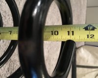
IMAG0891.jpg IMAG0905.jpg

24. Connect new sway bar links at sway bar. (15mm, 45 ft-lbs.) — Only if you're replacing the sway bar links as I did. Otherwise you probably left these joints connected.
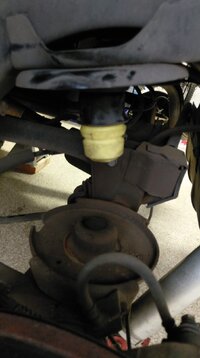
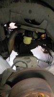
25. Connect new sway bar links at axle. (18mm & T55, 75 ft-lbs.)
IMAG0894.jpg IMAG0892.jpg

26. Check that all bolts are torqued to spec:
• Sway bar ends at axle (18mm & T55, 75 ft-lbs.).
• Track bar at axle bracket (15mm, 40 ft-lbs.).
• Drag link at right side knuckle (check cotter pin).
• Wheel lug nuts (Tire iron, 100 ft-lbs.).
• Shocks at frame (14mm open end & 16mm thin open end, 17 ft-lbs.). — Only if you removed the shock for a bump stop check.
• Shocks at axle (13mm long & 10mm box end, 21 ft-lbs~250 in-lbs.).
• Lower suspension arms at frame (21mm & 21mm box end, 130 ft-lbs.).

27. Measure the front spring height and shock position.
IMAG0903.jpg IMAG0904.jpg IMAG0902.jpg
 
Last edited:
Rear Spring Removal

1. Place the vehicle on a level surface with the transmission in park (or in gear for a MT), the transfer case in 2H and the parking brake set.
IMAG0907.jpg

2. Measure the rear spring height and shock position. — I think you're supposed to measure the height of the spring, but the spring perches make that difficult. I just measured from the lips of the perches.
IMAG0915.jpg IMAG0913.jpg

3. Disconnect sway bar ends at axle. (15mm/18mm, 40 ft-lbs.) - FSM says to do this after raising and supporting the vehicle, but the bolts are likely to be under load at that point. I found it easier to do this before putting the vehicle on jack stands.
IMAG0923.jpg IMAG0924.jpg

4. Remove the track bar from the frame bracket. Loosely tie the track bar to the bracket in a position clear of other components. (15mm/18mm, 74 ft-lbs.) — This is a tight space to work in, and a bolt with a lot of torque. I managed to get by with a 15mm socket and an 18mm box end wrench, but an 18mm ratcheting box end would have been ideal. FSM says to raise and support the vehicle first, but the bolt is likely to be under load at that point. I found it easier to do this before putting the vehicle on jack stands.
IMAG0926.jpg

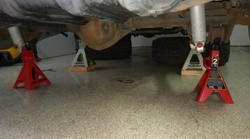
5. Chock front wheels. Raise and support the vehicle.
IMAG0929.jpg IMAG0930.jpg

6. Position a hydraulic jack under the axle to support it.
IMAG0931.jpg

7. Remove the wheel and tire assemblies. (Tire iron, 100 ft-lbs.)
IMAG0932.jpg IMAG0934.jpg

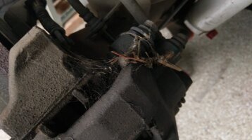
At this point, I discovered that Brown Widow spiders had been using my brake calipers as nests for their egg sacks. Seems like it could get hot in there, and Brown Widow webs collect a lot of debris. Not a good combination, so I cleaned them out.
IMAG0933.jpg

8. Support the axle with jack stands.
IMAG0935.jpg

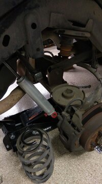
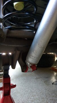
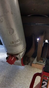
9. Disconnect the rear shocks at the lower mountings. (15mm/18mm, 74 ft-lbs.)
IMAG0939.jpg IMAG0938.jpg

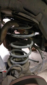
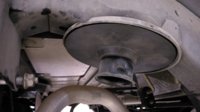
10. Lower the left side of the axle until the spring is free from the upper mount.
IMAG0940.jpg

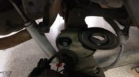
11. Remove the left spring. — Way easier than the front springs. The spring just slides out.
IMAG0941.jpg

12. Return the left side of the axle to the starting position and support with jack stands.
IMAG0952.jpg

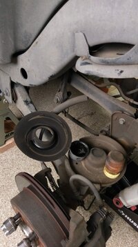
13. Pull the left jounce bumper out of the bump stop cup. — Only necessary if you're replacing it or the isolator.
IMAG0944.jpg

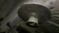
14. Remove the left bump stop cup. (15mm, ?? ft-lbs.) Remove the left upper spring isolator. — Only necessary if you're replacing the isolator.
IMAG0945.jpg

15. Install the new spring isolator in the top spring mount Reinstall the left bump stop cup. (15mm, ?? ft-lbs.) — I couldn't find the torque spec for this bolt so I just tightened about as much as it was when I found it.
IMAG0946.jpg

16. Lower the right side of the axle until the spring is free from the upper mount.
IMAG0949.jpg

17. Remove the right spring.
IMAG0951.jpg

18. Pull the right jounce bumper out of the bump stop cup.
IMAG0955.jpg

19. Remove the right bump stop cup. (15mm, ?? ft-lbs.) Remove the right upper spring isolator.
IMAG0956.jpg

20. Install the new spring isolator in the top spring mount. Reinstall the right bump stop cup. (15mm, ?? ft-lbs.) — I couldn't find the torque spec for this bolt so I just tightened about as much as it was when I found it.
IMAG0960.jpg

21. Return the right side of the axle to the starting position and support with jack stands.
IMAG0947.jpg

22. Measure the old spring lengths and the new spring lengths. — The difference here wasn't as much as the front springs. The old springs were just a little less than 1/2" shorter than the new springs.
IMAG0943.jpg IMAG0966.jpg IMAG0967.jpg
 
Last edited:
Rear Spring Install

(Pics soon!)

1. Install the new jounce bumpers in the bump stop cups. — Only if you're replacing them.

2. Lower the left side of the axle until there is room to install the new spring.

3. Install the new left side spring. — I had no trouble sliding the spring in.

4. Return the left side of the axle to the starting position and support with a jack stand.

5. Lower the right side of the axle until there is room to install the new spring.

6. Install the new right spring. — I had no trouble sliding the spring in.

7. Return the right side of the axle to the starting position and support with a jack stand.

8. Install the rear shocks at the lower mountings. (15mm/18mm, 74 ft-lbs.) — I had to muscle the shocks back to the right length to get them to line up. I found it easiest to compress them a little too far and let them extend back into place.

9. Install the wheel and tire assemblies. (Tire iron, 100 ft-lbs.)

10. Remove the supports and lower the vehicle.

11. Install the track bar to the frame bracket. NOTE: Use dry steering or a ratchet strap if necessary to realign the track bar to the bracket. (15mm/18mm, 74 ft-lbs.) — Gentle dry steering is the easiest way to line up the track bar if you have someone to help you. This bolt requires a lot of torque and is in a tight spot. I managed to get by with a 15mm socket, an 18mm box end wrench and some patience. An 18mm ratcheting box end wrench would be ideal.

12. Connect sway bar ends at axle. (15mm/18mm, 40 ft-lbs.) — For a Jeep at stock height, these should line up without any issue.

13. Check that all bolts are torqued to spec:
• Sway bar ends at axle. (15mm/18mm, 40 ft-lbs.)
• Track bar at frame bracket. (15mm/18mm, 74 ft-lbs.)
• Wheel lug nuts. (Tire iron, 100 ft-lbs.)
• Shocks at lower mountings. (15mm/18mm, 74 ft-lbs.)

14. Measure the rear spring height and shock position.
 
Last edited:
I’ll be keeping an eye out on this. I have sway bar Links for the front (no puller tool though) 32x11.5x15, 15x8 TM wheels, and 2” B.B. that needs to go on

I will need to pick up springs too mine are showing 10” front and 6” rear. I suppose this is normal after 250k

Thanks


Sent from my iPhone using Tapatalk
2005 RHD TJ Sport
2010 BMW 528xi
 
Last edited:
  • Like
Reactions: Chris and Fonz54
I have sway bar Links for the front (no puller tool though) 32x11.5x15, 15x8 TM wheels, and 2” B.B. that needs to go on

I will need to pick up springs too mine are showing 10” front and 6” rear. I suppose this is normal after 250k

Thanks


Sent from my iPhone using Tapatalk
2005 RHD TJ Sport
2010 BMW 528xi

I'd say get the puller tool. I got one from Home Depot, but it's not a precision tool and you could probably get a cheaper one somewhere else. FSM says you need a puller tool for the sway bar links and for the drag link end. After watching all the ham handed ways that people on YouTube smashed up their Jeeps trying to free these joints, I'd definitely go with the official tool.

The puller tool is kind of finicky to use, since the jaws are going to pop out a dozen times before you get the joint free, but I think it's worth being patient and sticking with it. One good trick — I'll add it to the post above — is to turn the steering to the left before trying to free the drag link joint. That gives you a better space to set the puller jaws on the joint. Also, make sure the bolts on the tool are snug, otherwise it will never stay in place.

At 10" front and 6" rear, you're going to be amazed what new springs will do for you!

Also, if you're going for 32x11.5R15 tires, based on what I saw with my 31x10.5R15s, you're going to need about an inch of backspace so the tire sidewalls can clear the spring perch when you're flexed and steering even a little off center. I hope your new TM wheels give you some extra space!
 
Absolutely excellent right up, this should prove to be incredibly helpful to members in the future.

It gets a bit more difficult when you're adding lift springs. My 4" springs for instance are so much longer than stock that you really have to let that front axle droop in order to get them in! But still, the procedure is more or less the same.
 
  • Like
Reactions: fuse
Thank you very much for sharing your install; great documentation!

The fee length of Moog 3229 rear spring. It's an inch shorter than the 3227 for loaded Jeeps.
Moog Rear 3229.jpg
 
For those tie rod ends...you might want to get a different puller. The type you used will work in a pinch, but as you've seen, the jaws have a tendency to slip off. That style puller is designed for pulleys, flywheels, and other disk type attachments to shafts. For a Tie Rod, something like this works MUCH better.

32J052_AS02?$mdmain$.jpg


The U'shaped cutout goes around the tapered end of the TRE (under the boot), and the bolt forces the joint apart.
 
  • Like
Reactions: fuse
I think they are 4.75
No 3.75

I have the stock 15X8.0 "Ravine" Aluminum Wheels, which supposedly have 5.5" backspace (I haven't measured). For my tires, I probably should have 5.0" or 4.5" backspace. For 32x11.5 tires, I would guess 4.5" or maybe 4.0".

But I haven't messed around with tires too much yet, and there are definitely people here who know a lot more than me about that.
 
Rear Spring Install

(I thought I'd be able to edit the prior post, but I guess there's a time limit on that.)

1. Install the new jounce bumpers in the bump stop cups. — Only if you're replacing them.
IMAG0997.jpg IMAG0996.jpg

2. Lower the left side of the axle until there is room to install the new spring.

3. Install the new left side spring. — I had no trouble sliding the spring in.
IMAG0998.jpg

4. Return the left side of the axle to the starting position and support with a jack stand.
IMAG0999.jpg

5. Lower the right side of the axle until there is room to install the new spring.
IMAG1003.jpg

6. Install the new right spring. — I had no trouble sliding the spring in.
IMAG1004.jpg

7. Return the right side of the axle to the starting position and support with a jack stand.
IMAG1005.jpg

8. Install the rear shocks at the lower mountings. (15mm/18mm, 74 ft-lbs.) — I had to muscle the shocks back to the right length to get them to line up. I found it easiest to compress them a little too far and let them extend back into place.
IMAG1007.jpg IMAG1009.jpg

9. Install the wheel and tire assemblies. (Tire iron, 100 ft-lbs.)
IMAG1010.jpg IMAG1011.jpg

10. Remove the supports and lower the vehicle.
IMAG1012.jpg

11. Install the track bar to the frame bracket. NOTE: Use dry steering or a ratchet strap if necessary to realign the track bar to the bracket. (15mm/18mm, 74 ft-lbs.) — Gentle dry steering is the easiest way to line up the track bar if you have someone to help you. This bolt requires a lot of torque and is in a tight spot. I managed to get by with a 15mm socket, an 18mm box end wrench and some patience. An 18mm ratcheting box end wrench would be ideal.
IMAG1015.jpg

12. Connect sway bar ends at axle. (15mm/18mm, 40 ft-lbs.) — For a Jeep at stock height, these should line up without any issue.
IMAG1017.jpg IMAG1018.jpg

13. Check that all bolts are torqued to spec:
• Sway bar ends at axle. (15mm/18mm, 40 ft-lbs.)
• Track bar at frame bracket. (15mm/18mm, 74 ft-lbs.)
• Wheel lug nuts. (Tire iron, 100 ft-lbs.)
• Shocks at lower mountings. (15mm/18mm, 74 ft-lbs.)

14. Measure the rear spring height and shock position.
IMAG1027.jpg IMAG1029.jpg

15. Check out how awesome your Jeep looks with new springs!
IMAG1031.jpg
 
Thank you very much for sharing your install; great documentation!

The fee length of Moog 3229 rear spring. It's an inch shorter than the 3227 for loaded Jeeps.
View attachment 50379

I used the Moog 3226 front springs and 3227 rear springs. As you can see above, the free spring lengths pretty close to spec: 17-3/16" and 12-1/4".

The old springs I replaced were 16-3/8" and 11-13/16". But in addition to losing some free length, I think the spring rate wasn't what it used to be.

So I went from 11" installed height to 12" in front, and 7-1/4" installed height to 8-1/4" in the rear.

I actually had ordered the Moog 3224 and 3229 springs first, but decided not to use them when I found out that the new front springs were shorter than my old front springs.

Moog's online catalog identifies the 3226/3227 sets as replacement parts for Rubicon models, and the 3224/3229 sets as replacement parts for all other models, but I don't think they have it right. I think the 3226/3227 sets are for 4.0L models (possibly with AT), and the 3224/3229 sets are for 2.5L models.
 
  • Like
Reactions: SSTJ
I just saw this in the How to Align Your Jeep Wrangler thread, and I wish I had seen it when I started this job. Learning the names of all the front suspension and steering parts and figuring out where they are was one of the first hurdles.

alignment01.jpg


Also, now that I've been driving with the new springs, I notice that my steering wheel is just slightly off center. It used to be exactly centered. PO said he had the death wobble fixed, and the tie rod ends looked newer than other parts, so it may be that he had the alignment done with the old sagging springs. I may just give the drag link a twist and see if I can line the steering wheel back up.
 
That would have been great to have! What is that tool and where do you get it?
Its called a ball joint separator. You can get them from Amazon, Harbor Freight, etc. I haven't seen them at auto parts stores though, but maybe in the rental programs. Look at a "Front end service kit."
 
  • Like
Reactions: fuse
Something has been bugging me about this for a while, so I figured I should do something about it. I didn't have the torque spec for the bolts that hold in the bump stop cups, but the FSM does have generic torque specs for bolts based on their size and grade. Best I can tell, the bump stop cup bolt is a 10.9 M10 bolt, which means the recommended torque is 45 ft-lbs.
 
  • Like
Reactions: SSTJ
For those tie rod ends...you might want to get a different puller. The type you used will work in a pinch, but as you've seen, the jaws have a tendency to slip off. That style puller is designed for pulleys, flywheels, and other disk type attachments to shafts. For a Tie Rod, something like this works MUCH better.

View attachment 50391

The U'shaped cutout goes around the tapered end of the TRE (under the boot), and the bolt forces the joint apart.
Thank you again for this recommendation, @Mike_H! I've used this tool three times in the last couple of days, and while it's not always easy to slot it in at the TRE, it's a heck of a lot better than that other puller tool.
 
  • Like
Reactions: Mike_H
Thank you for the extremely helpful guide.

I have a quick question. Other guides for similar work that I read online (like here) don't include removing the track bar. What's the purpose in your approach? I noticed in the bump stock check you put it back on again.