Bussmann Auxiliary Fuse and Relay Module Installation

Steel City 06

TJ Expert
Supporting Member
Joined
Mar 12, 2019
Messages
4,499
Location
Pittsburgh, PA
The following is a brief writeup of how to install a Bussmann auxiliary relay and fuse panel into a Jeep or any other vehicle.

82093


If there is any interest in this topic, please respond and I would be happy to go into more detail on how these boxes work or how to install them.
Ask any questions. I am attempting to keep this shorter, so I am purposely skipping some explanations, part numbers, links, etc.

This writeup assumes the person performing work is competent with electronics, and understands principles and rules behind electrical circuits.
Any electrical work is done at your own risk. Consult an automotive electrical professional.

The purpose of the Bussmann install is to provide a single location to hook up any and all auxiliary circuits 30 amps or smaller to the electrical system. The Bussmann panels provide a location to install both fuses and relays. Some configurations also include internal bussing, making wiring of the system far easier. Using a Bussman fuse and relay panel significantly cleans up the wiring in your Jeep. No more bird's nests of relays, fuses, and wires going everywhere. Plus it makes troubleshooting, connecting, and disconnecting electrical accessories far simpler.
 
There are two sizes of Bussmann fuse and relay boxes that this writeup covers.

The first, and smaller size, is the Series 15300 RTMR (Rear-fed Terminal Mini fuse and Relay) panel.
This box can be bought in several configurations, and can house up to 20 mini-fused circuits without relays, or 10 mini-fused circuits with up to 5 of those circuits including relays.
The box can be purchased with varying degrees of internal bussing. The internal bus can support up to 100 amps of continuous load.
http://www.cooperindustries.com/con...r_distribution_modules/series_15300_rtmr.html

The second, and larger size, is the Series 15400 RFRM (Rear-fed Fuse and Relay Module).
This fuse panel can support 40 individual mini-fused circuits, and can hold up to 10 micro relays.
This can be bought without any internal bussing or with two internal busses that can support 100 amps of continuous load each.
http://www.cooperindustries.com/con...series_15400_rfrmrear-fedfuserelaymodule.html

Click on the PDFs on the linked pages to get a better understanding of how the panels are bussed.
There are other configurations that include wiring harnesses and other features that I will not cover in this write-up.

82095


The panels accept primarily standard mini-fuses, or the same type you find behind your glovebox. Fuses generally range from 5 amps to 30 amps.
The panels accept a micro relay which is different than the relays under your hood. The relays can support up to 35 amps, and can be SPST or SPDT and resistor or diode type depending upon your needs.
 
The first step is to decide which RTMR/RFRM you need. First, count all of the circuits you currently have that are 30 amps or less that you would like to add to the RTMR/RFRM. Second, count how many circuits you have that will require relays. Typically, most circuits 10 amps or larger will have relays. Finally, add in any future electronics you might even consider adding. Think about all the lights, air compressors, stereo accessories, pumps, kill switches, two-way radios, cameras, chargers, trailer brake controllers, electric line brake locks, e-lockers, computers, horns, alarms, GPS trackers, or other accessories you might add. If you end up with 10 or more circuits or 5 or more relays, choose the RFRM. If not, choose either the RTMR or RFRM. It is far easier to add circuits to an existing RFRM than it is to wire in a second RTMR.

The second step is to check that you have somewhere to mount the fuse box(es) of your choice. The RTMR and RFRM are IP66 water resistant, so they can take some splashing, as long as you are careful to use cable seals on every cavity. They cannot be immersed. Look at the dimensions on the linked web pages. You may have to get creative with the mounting solution.

I chose to mount it on top of the inner fenders where the factory cruise control mounts. I jury-rigged some brackets for now. Don't copy these brackets. Make sure whatever mounting solution you choose is sturdy, doesn't vibrate, and doesn't create a risk of shorting. Be sure to keep the space behind the box clear. Bussmann makes brackets that fit the RTMRs.

82101


To look for the correct box, you will need to search for the part number that meets your needs. Use the PDF files to generate your part number. In my case, I ordered the Bussmann 15401-2-0-1-0A RFRM. This gives me a RFRM with 40 bussed fuse slots and 10 micro relay spots, 10-32 mounting holes, 2 - 100 amp bus bars, and a water resistant cover.

You will also need to order the correct Metri-Pack 280 series connectors, cable seals, cavity seals, terminal covers, and relays. I can list part numbers if requested. For the relays, I ordered 10 SPDT relays, because they were not any more expensive than SPST relays. The SPDT allow for more wiring configurations.

82098

82099


I ordered all of the above components through Waytek wire. Some of the components, namely the seals and connectors, have a minimum order quantity of 50 or even 100. Find a buddy you can split the packs with if you don't need them all. I find it is good to have a variety of connectors and seals on hand so I can add a circuit without having to order any parts. Having an assortment of mini-fuses is also handy.
 
  • Like
Reactions: cpwolf
In addition, you will need to run a master power cable from the battery to the panel. (The remainder of this How-To will focus on the bussed panels only.) This cable must be appropriately sized, and must be fused no matter how long or short. I recommend a 4 AWG cable for each bus. Be sure to double check an ampacity chart for your application. The general rule for fuse sizing is to size the fuse at approximately 125% of the maximum expected continuous load. In other words, the maximum expected continuous load is approximately 80% of the fuse rating. The busses are rated at 100 amp each, so the maximum appropriate fuse size to use is a 125 amp fuse. Ideally, the fuse on each bus would be 100 amps or smaller. Reference the fuse manufacturer's blow delay curve to help select the right fuse. Smaller fuses should be used if you don't expect to use the full capacity of the RTMR/RFRM bus.

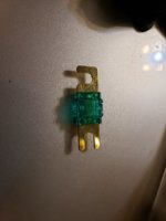
The master fuse(s) must be located as close to the battery as possible. In the event of a collision, rollover, internal short in the Bussmann panel, loose connection, or other unfortunate event, a short on a non-fused wire of that size may cause a fire, and reduce your Jeep to a burnt hulk. I recommend fusing within a 12" cable run of the battery. Note that a fuse does not guarantee that a fire does not start. It merely reduces the odds, much like a seatbelt reduces the odds of severe injury in a wreck. Thus, ensure all connections are secure and properly insulated. Personally, I would even fuse a winch connection, even if it requires a 500+ amp fuse to do so. ANL fuses are available in sizes from 35A to 750A.

I ran a 2/0 AWG cable to a double ANL fuse holder, installed 2 - 125 amp fuses, and ran 4 AWG cables from the fuse holder to the Bussmann panel. 1/0 AWG or two separate runs of 4 AWG to the ANL fuses would have been sufficient, but I had 2/0 left over from a different install. I used standard crimp ring terminals to connect the wire to the battery and the Bussmann panel. If you use ring terminals, ensure the hole is properly sized for the stud. An oversized hole will result in poor contact, and potentially overheating and even fire.

82102

Note: Do NOT connect the terminal to the battery with the fuses in the ANL fuse holder until the Bussmann panel is bolted into place and the connections secured. I recommend not installing the fuses until the panel is secured. Failure to adhere will cause a short and blow up your new fuses (or worse) if any positive connection hits the body of the car.
 
  • Like
Reactions: B00mb00m
Next, you MUST add an additional ground strap from the battery to the body. The stock ground strap is sufficient for the electrical loads that the OEM installed and anticipated, but is NOT sufficient for the OEM loads combined with the loads you are adding. Leave the OEM wiring untouched, and install a second adequately sized ground strap. I chose to use a very short run of 2 AWG as shown. Failure to do this will not only cause unnecessary voltage drop, but could even cause a fire in a worst case scenario as the stock ground strap becomes overloaded.
Be sure to check the quality of the ground by comparing the current flowing in the stock ground strap to the aftermarket ground strap. Ideally, the aftermarket strap takes the majority, but not all, of the load. Multiple or larger straps may be required due to other electrical accessories like winches, high output alternators, large stereos, etc. I will likely either add a second run of 2 AWG to another location on the body or swap the existing one for 2/0 in the future.
Look up the "Big 3 Upgrade" for automotive electrical wiring if you are using a larger than stock alternator. Some high power alternators, such as the 370 amp models, have enough power to melt stock or poorly installed wires.

82103

(Note the ANL fuse holder is currently hidden behind the battery. I intend to mount it above the PCM once I remove the cowl to ensure I'm not drilling into anything.)

At this point, the major connections are complete. Next is to install the wiring for the individual circuits.
 
I chose to pre-wire the fused power from the fuse slots to the relay as shown by the small green loops. For circuits I am not using yet, I simply leave the fuse slot empty, so no power is fed the the relay.

For circuits that require constant power, wiring is very simple. My 300W RMS subwoofer amplifier is powered by a single 10 AWG wire connected to the first open fuse slot. To provide power to the amplifier, I simply insert a 30 amp fuse, as recommended by the amplifier manufacturer, into the slot. (The amplifier has its own internal relay that is controlled by the turn-on of the stereo.)

82104


For circuits that require switched but non-relay fed power, wiring is also relatively simple. For example, if I choose to install KC Hilites LED scene lights, I would not bother to run a relay, since the current draw for a pair is only 3.2 amps. A wire would be run from an open fuse slot to the switch in the cab, and then from the switch to the lights. A 5 amp fuse would likely be more than sufficient for the pair of lights.

For circuits that require switched and relay-fed power, wiring is relatively straightforward. In the 3rd and 4th relay positions I have the relays that power my KC Spots. The spot lights supposedly take around 22 amps combined (130 watt bulbs). To run them on a switch without a relay would result in a large voltage drop and reduced performance, and could even be a fire hazard. To power them, a switched signal wire from anywhere in the cabin (in my case from a fuse tap inserted behind the glovebox) is run to the switch. The switch output is then run to the relay signal. The other signal pin on the relay is then grounded. (This signal circuit uses a very small amount of current - usually 1/10 amp or less.) The relay power has already been hooked up from the green loops to a fuse slot, so the relay has power. The Normally Open (NO) contact on the relay is then hooked up to the lights.

I chose to run each individual KC light on a separate relay, hence why there is a relay for each individual bulb. This turned out not to be necessary, as the amp draw was far less than I expected - close to 8 amps per bulb.

To size the individual fuses, the best method is to use the manufacturer's recommendation. For example, if a set of 100 watt lights come with a 25 amp fuse installed in its wiring harness, then a 25 amp fuse would be appropriate for the 2 - 100 watt bulbs on one circuit.
However, when this is not available, estimate using the 125% rule. A 100 watt bulb rated at 12 volts would draw 8.3 amps at 12 volts. A pair of these would result in a target fuse size of 20.8 amps, which is close enough to a 20 amp fuse that I would use the 20 amp. Consult the manufacturer of the accessory to determine the appropriate fuse and wire size.
 
82105

Underside of the RFRM. The green rubber pieces are removable cavity plugs to prevent water from getting into open holes. Note that every wire is sealed with a cable seal. The terminal post caps are missing in these photos.

(Unfortunately, I'm not the neatest person when it comes to cable management.)
 
When between fuse sizes, choose the higher fuse size ONLY IF ALL WIRING PAST THE FUSE CAN HANDLE THE FUSE MAXIMUM CURRENT. For example a 27 amp ideal fuse would typically be filled with a 30 amp fuse, provided the wiring on the fused side is of adequate size to handle 30 amps in the event of a partial short. The fuse does no good if the wiring burns up before the fuse blows. Again, consult the equipment manufacturer to determine the appropriate wire and fuse size.


Not all relay circuits have to be triggered by a switch. For my KC fog lights, I actually ran a wire from the stock fog light plug to the relay operating the fogs. This allowed me to use the higher amperage KC fog lights while still retaining the factory fog switch and the factory relay action that disables the fogs when the high beams are turned on, as required by state law. I then downsized the stock 20 amp fog light fuse to a 5 amp fuse, since all the OEM relay now does is power another relay.
 
One of the advantages of the RTMR/RFRM is that the panel can be re-configured as circuits are added or changed. I jury rigged a tool out of a paperclip to remove the pins from the panel without damage to the panel itself.

As a note, any time the RTMR or RFRM is being worked on, disconnect the power cable from the battery. All it takes is one misplaced wrench stroke or one bump of the box to create a short.

The sum of all current draws on one bus of the panel must not exceed 100 amps. This does not necessarily mean that all the micro fuses need to add up to 100 amps or less. This means that more than 100 amps of accessories on one bus cannot be turned on at the same time. Plan ahead on how you wire your circuits to each bus to ensure this maximum is not exceeded. For example, I would find it unlikely that I would be running two air compressors at the same time as my stereo is set to the maximum volume. But I might be running the compressors at the same time as all the halogen lights. So it may be smart to have the compressors and the amplifiers on the same bus, but the lights wired on the opposite bus.

Circuits requiring fuses larger than 30 amps should be separately fused and wired to the battery or other appropriate electrical connection. Don't expect to be able to insert any wire larger than 10 AWG into the panel.

Be sure to check the amperage rating on the relays you purchase. The current rating on the NO (Normally Open) pin may not be the same as the NC (Normally Closed) pin. Also be sure to understand the differences between diode and resistor type relays.
 
Nicely done! IMHO, this is the way to go if you want to start doing lots of aftermarket wiring. It certainly looks factory.
 
  • Like
Reactions: Steel City 06
Be sure to post some pictures when you do! I don’t have any photos of the smaller RTMR.
That was about 5 years ago, and I'll have to look to see if I still have any. I may link to a thread on WF if that's ok here.
One of the reasons I built the Bussman was to get a few extra circuits, and to rewire my headlights with larger wiring. The factory wiring had 1.5 volts voltage drop between the battery and the headlights. After the upgrade the voltage drop was .3 volts. Doesn't sound like much but it is a big difference on a 12 volt system. The standard headlights were considerably brighter just doing this upgrade.

I don't know the rules regarding outside links. You'd have to check with the administrator @Chris .

For incandescent and halogen bulbs, small changes in voltage do make a big difference.

First off, power = voltage^2 / resistance.
Hence going from 12 volts to 13.2 volts at the bulb (engine running) will result in a 21% increase in power.

Second, incandescent and halogen bulbs become more efficient the harder they are driven. I don't know the actual formula, but it has to do with the change in filament temperature changing the black body emission spectrum more into the visible range.

Manufacturers of incandescent and halogen bulbs have to balance efficiency vs life. This is why people complain about the brightest headlight bulbs burning out quickly or about how long life bulbs aren't bright enough.

Halogen bulbs are the same as an incandescent but are filled with inert gas and iodine/bromine gas. The halogen gas actually extends the life of the filament at higher temperatures (increasing efficiency and brightness) by re-depositing evaporated tungsten, so the manufacturers can run the bulbs far hotter (or longer life) than a typical incandescent.

LEDs typically have their own internal voltage regulator and are typically not affected by small changes in voltage.
 
Last edited:
  • Like
Reactions: Rich1961
While I was under the hood, I compared the amperage flowing through the stock strap and through the new ground strap. Note the difference. Shows how inadequate the stock ground is.
82448

82449


And for fun I also was curious if the radiator supports were the main ground path:
82450
 
  • Like
Reactions: bedhed and Rich1961