Hooke Road Driver Side 4-switch Pod Panel Installation

Firefighter2

New Member
Original poster
Supporting Member
Joined
Oct 15, 2023
Messages
12
Location
Southern Illinois
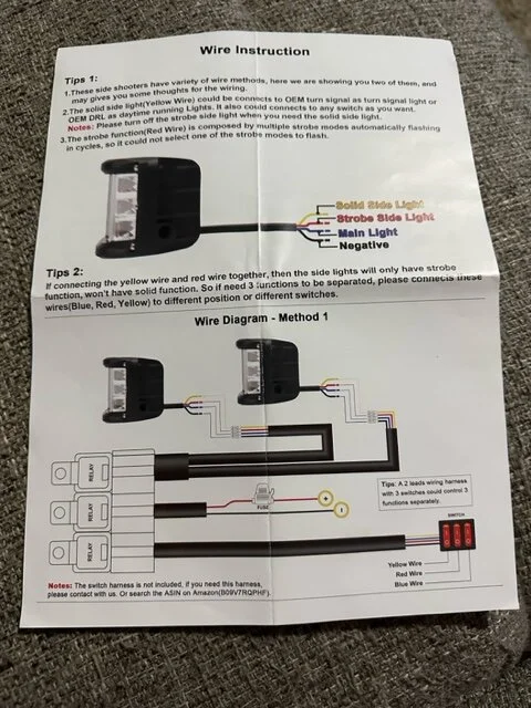
I recently purchased a Hooke Road driver Side 4-Switch Pod Panel that goes in place of the speaker trim cover. The 4 rocker switches are wired in series with one red lead and one black lead coming out of the first switch. Then there is a white lead coming off of each switch and each switch has an open terminal blade. I haven't been able to find any kind of wiring schematic for this setup to know what wire goes to what. I am adding two sets of led drive lights with blue side strobes. I have attached a picture of the switch pod panel, the back side of the panel, and a picture of the wiring harness that comes with the strobes. In the wiring diagram that goes with the strobes it shows three switches. I am thinking that the yellow, blue, and red wires going to the switch in the harness diagram will each go to an individual white switch wire on the pod panel. What I am not sure about is where the red and black leads coming from the first pod panel switch and the red and black wire coming out of the middle relay of the harness assembly. I am guessing that since the harness assembly includes the relays then I won't utilize the open terminal blade that is present on each switch. Any clarity or recommendations that anyone can provide would be greatly appreciated.
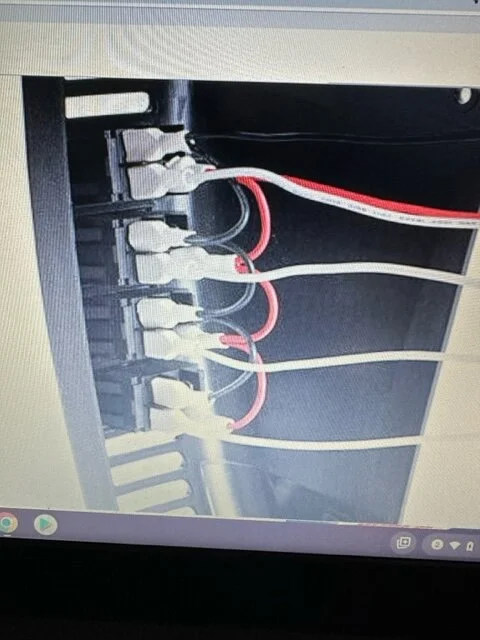
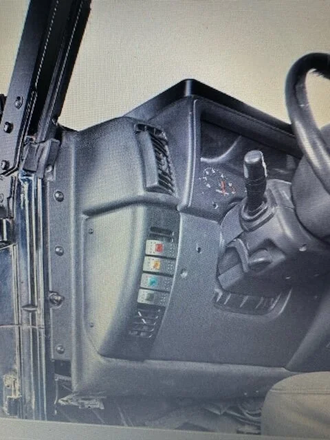
image2.webp


image1.webp


image0.webp
 
the red wire on your switches is going to come from a 12V supply, either switched (if you only want the lights powered while the jeep is on) or constant (if you want to have the lights on regardless of the key being present). I'm personally a fan of using a tap-a-fuse on either the radio (switched) or fog lights (constant) fuse inside the glovebox and running the wire behind the dash to your switches, but there are other nearby wires that can supply either function.

The black on the switches needs to be grounded somewhere. The 3 colors will go to each of the 3 switches to control the 3 functions, with the black being the ground. Not sure why that portion of the harness sends the ground back to the switches, but from the diagram it appears that's what happens. You could ground it to the same place you ground the switches.

I don't really understand the wiring at the relays specifically, there must be some magic going on that connects the "umbilical" to the different relays.

I would definitely do this outside the vehicle to test that it's going to work how you want before you start mounting switches and committing to wiring choices.


Where at in SOIL?
 
the red wire on your switches is going to come from a 12V supply, either switched (if you only want the lights powered while the jeep is on) or constant (if you want to have the lights on regardless of the key being present). I'm personally a fan of using a tap-a-fuse on either the radio (switched) or fog lights (constant) fuse inside the glovebox and running the wire behind the dash to your switches, but there are other nearby wires that can supply either function.

The black on the switches needs to be grounded somewhere. The 3 colors will go to each of the 3 switches to control the 3 functions, with the black being the ground. Not sure why that portion of the harness sends the ground back to the switches, but from the diagram it appears that's what happens. You could ground it to the same place you ground the switches.

I don't really understand the wiring at the relays specifically, there must be some magic going on that connects the "umbilical" to the different relays.

I would definitely do this outside the vehicle to test that it's going to work how you want before you start mounting switches and committing to wiring choices.


Where at in SOIL?

Thanks for the input. Do you know what the open terminal blade on each switch is for? I currently have a lights on the front bumper that runs off a single switch. The switch has three prongs on the back of it. A red wire is on one terminal that runs back to the fuse panel behind the glove box. The middle terminal has a blue wire that goes back to a 30A relay in the engine compartment. The other terminal has a black wire that is going to ground. I was wanting to move those lights to the 4th spot on the pod panel. How would I integrate that?
 
The open blade on the switch is probably where you move the red to if you want to make the switches light up all the time/only when on.

Do your lights on the bumper go through a relay (they probably should)? Either way, the red on the switch is from your power source (some 12V source that is live whenever you expect the switch to work). The blue wire to the 30A fuse is probably then going to the lights themselves (and thus we have answered the question about the relay; you're likely not using one). The black wire grounds the switch to light the led on the switch.

Probably.
 
the red wire on your switches is going to come from a 12V supply, either switched (if you only want the lights powered while the jeep is on) or constant (if you want to have the lights on regardless of the key being present). I'm personally a fan of using a tap-a-fuse on either the radio (switched) or fog lights (constant) fuse inside the glovebox and running the wire behind the dash to your switches, but there are other nearby wires that can supply either function.

The black on the switches needs to be grounded somewhere. The 3 colors will go to each of the 3 switches to control the 3 functions, with the black being the ground. Not sure why that portion of the harness sends the ground back to the switches, but from the diagram it appears that's what happens. You could ground it to the same place you ground the switches.

I don't really understand the wiring at the relays specifically, there must be some magic going on that connects the "umbilical" to the different relays.

I would definitely do this outside the vehicle to test that it's going to work how you want before you start mounting switches and committing to wiring choices.


Where at in SOIL?

I live in Flora. It is straight south of Effingham. Should the red wire coming off of the first switch of the pod panel be tied into the red fused wire shown coming off of the middle relay or do both of them need to be fused?
 
Then you probably know the Tolbert's. They actually live in Xenia, but there's no way you could be from Flora and not also know every person in Xenia.

Also, sad to hear about the Pizza Pit, that place was off the chain good.
 
I live in Flora. It is straight south of Effingham. Should the red wire coming off of the first switch of the pod panel be tied into the red fused wire shown coming off of the middle relay or do both of them need to be fused?

The red wire going into the switches wouldn't hurt to be fused, but it's going to be a very low draw circuit, just enough to light the LED on the switch and then excite the relay. The big fuse on your other circuit is necessary because it's supplying the load directly, not through a relay.