
Okay yeah. So off of this harness I ran one to the horn by accident. Should it go to the other wire on the clock spring?Ignore the colors focus on the pin locations the two wires for the clock sling in the center are the two for the cruise system the one on the outside goes to the horn relay.

You are using an out of date browser. It may not display this or other websites correctly.
You should upgrade or use an alternative browser.
You should upgrade or use an alternative browser.

Cruise Control Wiring Diagram Help
- Thread starter HuskerJeep
- Start date

Okay So it would go on the other red wire. I’ll move it over in just a second
I assume that’s why I had a high idle. Because if I’m not mistake the horn always has positive power soOkay So it would go on the other red wire. I’ll move it over in just a second
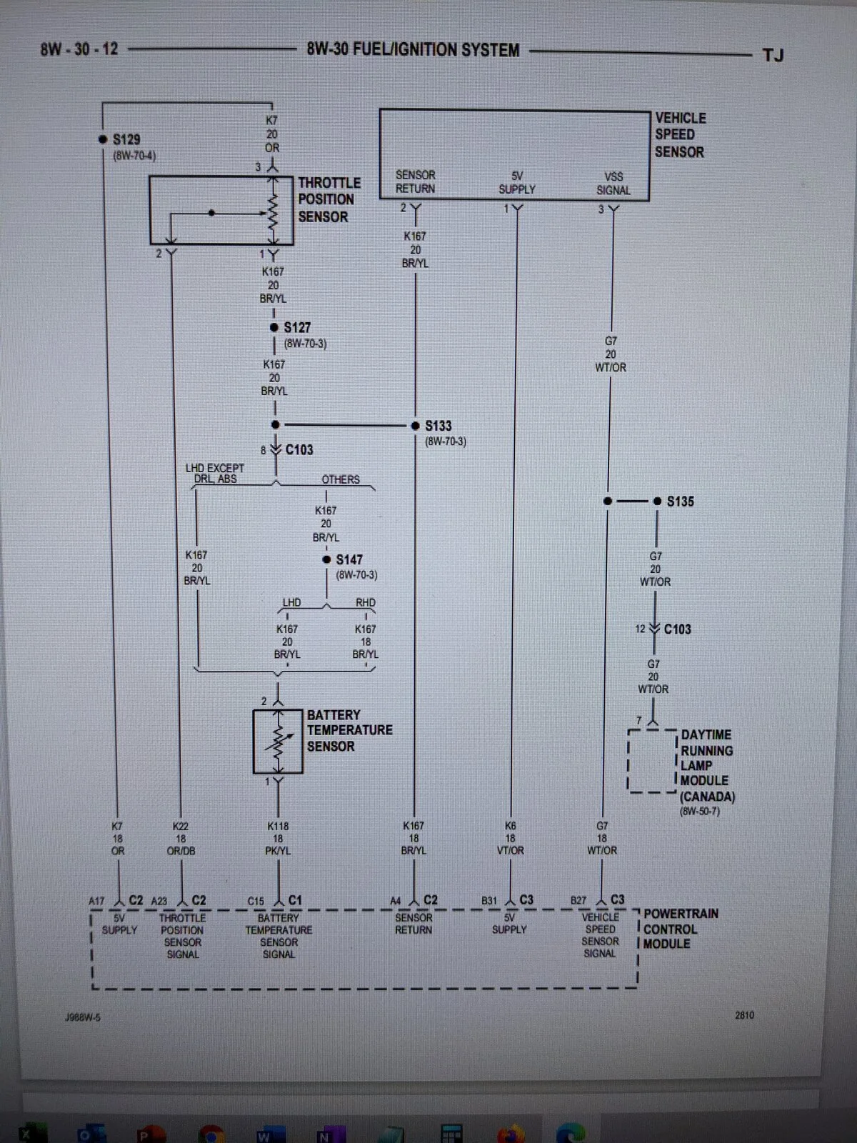
So where does the red wire that you have in with the red/light green wire go? there should be single line from the clockspring to the C32 the RD/LG and the BR/YL should go to splice into the temp sensor and to the A4 pin on the PCM C2 connector. nothing else is required.

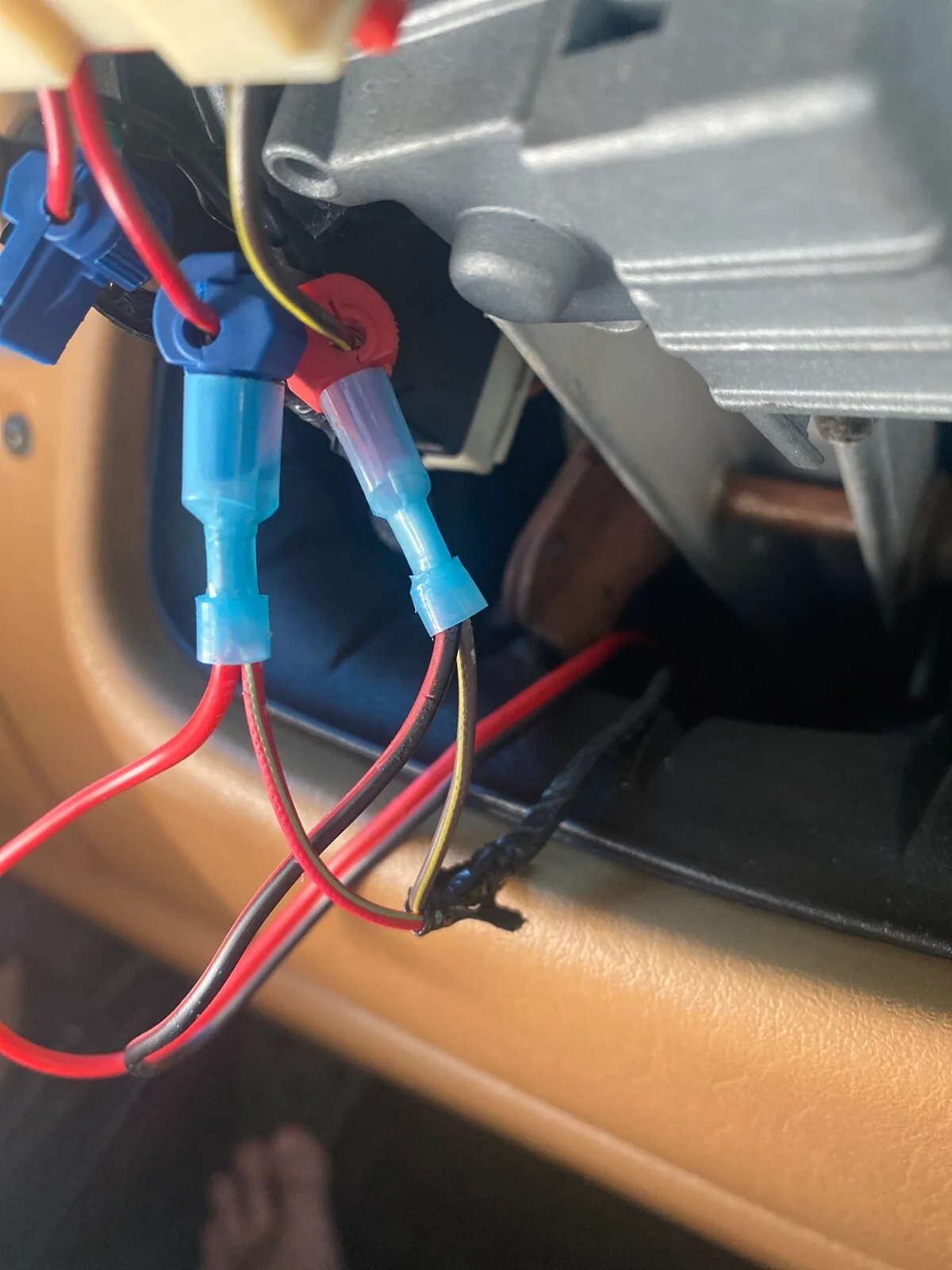
It has a normal idle again. But still no working cruise. This is how I have the wires tapped.
View attachment 253716
You need to Remove the steering wheels for thisIt has a normal idle again. But still no working cruise. This is how I have the wires tapped.
View attachment 253716
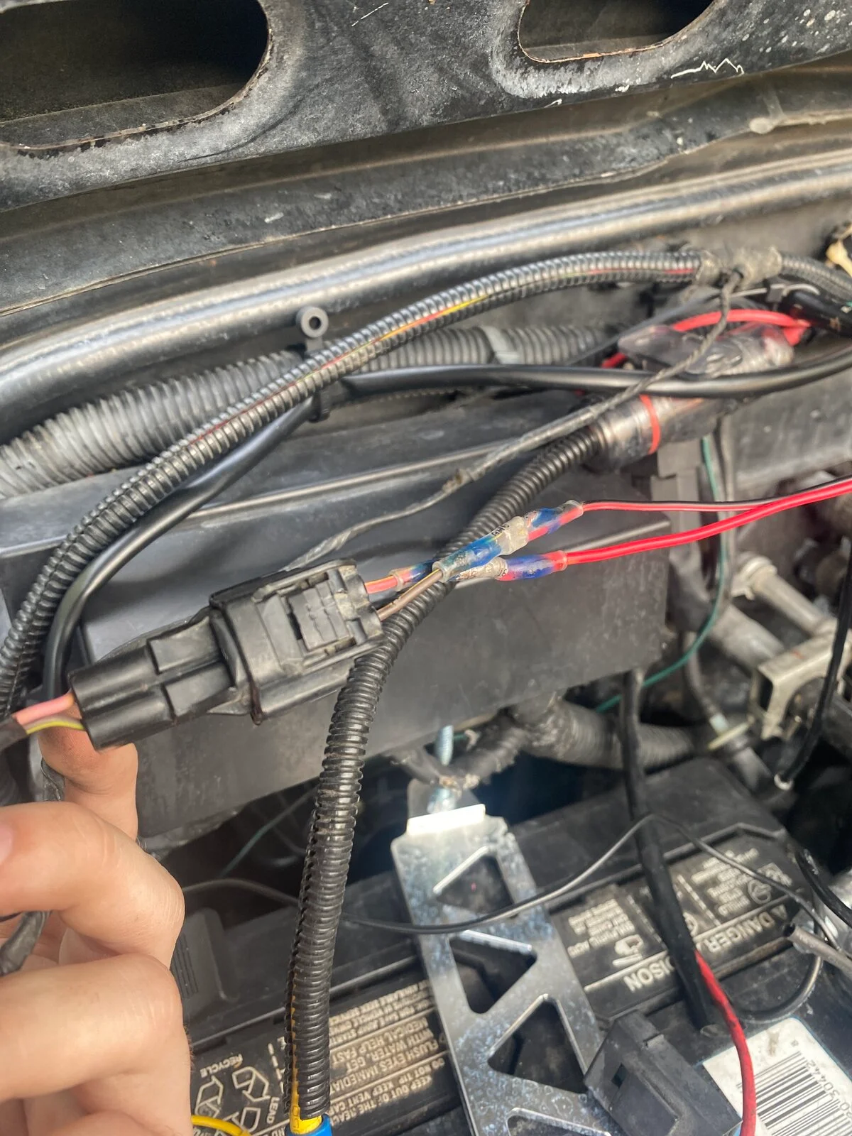
The red/green tracer off the c/s goes to the spot on the 2nd pic on the pcm,do you have the right clockspring?You need to Remove the steering wheels for this
Last edited:
That red wire goes to this connectorSo where does the red wire that you have in with the red/light green wire go? there should be single line from the clockspring to the C32 the RD/LG and the BR/YL should go to splice into the temp sensor and to the A4 pin on the PCM C2 connector. nothing else is required.
I changed the clock spring before I added the pins to the ecuThe red/green tracer off the c/s goes to the spot on the 2nd pic on the pcm,do you have the right clockspring?View attachment 253749View attachment 253749
I assume that is your plug for the battery temp sensor. If so it is wired wrong. The harness in your jeep already had the RD/LG and BR/YL wire by the looks of the picture where you tapped into them. Those wires most likely ended in the blue connector C108 in the dash by the steering column. Assuming the RD/LG and the BR/YL wires you ran are not spliced anywhere that is all you needed for the cruise control buttons. The red wire you ran form the battery sensor could have tapped into the harness by the PCM rather than running it all the way into the interior but regardless that wire needs to be spliced into the BR/YL wire instead foe the RD/LG wire.
Yes my batt temp was already wired inI assume that is your plug for the battery temp sensor. If so it is wired wrong. The harness in your jeep already had the RD/LG and BR/YL wire by the looks of the picture where you tapped into them. Those wires most likely ended in the blue connector C108 in the dash by the steering column. Assuming the RD/LG and the BR/YL wires you ran are not spliced anywhere that is all you needed for the cruise control buttons. The red wire you ran form the battery sensor could have tapped into the harness by the PCM rather than running it all the way into the interior but regardless that wire needs to be spliced into the BR/YL wire instead foe the RD/LG wire.
I was referring to this photo from Tycarver. There should be no splice to the Red/light green wire from the clock spring it goes directly to the PCM pin C32.
There is a second wire attached to the Brown/yellow wire that is Black/red If that wire goes to the plug show in the second photo and that is the battery sensor that one is OK. The battery sensor does splice into the Brown/yellow wire.
I assume this is a battery sensor plug. I hope you still have the factory wiring inact on the original battery sensor because the Pink/yellow wire goes to pin A4 on plug C2 of the PCM , There is no change required for that wire. The Brown/yellow wire from the original battery temp sensor needs to be connected to the Brown/yellow wire from the clock spring plug. I assume the Black/red wire from the first picture is the same Black/red in this picture if so it just needed to be spliced into the Brown/yellow wire on the battery temp sensor that should still be under the battery. Refer to the schematic after this picture.
Tycarver you already have a battery sensor and plug so ignore the one that came with the parts you bought, it is just a spare. make the connection from the clock spring to the battery temp sensor the Brown/yellow wire to the Brown/yellow wire. Connect the Red/light green wire from the clock spring to the C32 pin on the C1 plug of the PCM.
There is a second wire attached to the Brown/yellow wire that is Black/red If that wire goes to the plug show in the second photo and that is the battery sensor that one is OK. The battery sensor does splice into the Brown/yellow wire.
I assume this is a battery sensor plug. I hope you still have the factory wiring inact on the original battery sensor because the Pink/yellow wire goes to pin A4 on plug C2 of the PCM , There is no change required for that wire. The Brown/yellow wire from the original battery temp sensor needs to be connected to the Brown/yellow wire from the clock spring plug. I assume the Black/red wire from the first picture is the same Black/red in this picture if so it just needed to be spliced into the Brown/yellow wire on the battery temp sensor that should still be under the battery. Refer to the schematic after this picture.
Tycarver you already have a battery sensor and plug so ignore the one that came with the parts you bought, it is just a spare. make the connection from the clock spring to the battery temp sensor the Brown/yellow wire to the Brown/yellow wire. Connect the Red/light green wire from the clock spring to the C32 pin on the C1 plug of the PCM.
So I’ve tried to read this a few times and I’m a little lost the wires I ran and tapped into the clock spring eith are the ones I have circled here. The battery temperature sensor I have not messed with. And the wire on 32 I had to add to the pcm so I did not have that one before. Not sure if I’m on the same pageI was referring to this photo from Tycarver. There should be no splice to the Red/light green wire from the clock spring it goes directly to the PCM pin C32.
There is a second wire attached to the Brown/yellow wire that is Black/red If that wire goes to the plug show in the second photo and that is the battery sensor that one is OK. The battery sensor does splice into the Brown/yellow wire.
View attachment 253789
I assume this is a battery sensor plug. I hope you still have the factory wiring inact on the original battery sensor because the Pink/yellow wire goes to pin A4 on plug C2 of the PCM , There is no change required for that wire. The Brown/yellow wire from the original battery temp sensor needs to be connected to the Brown/yellow wire from the clock spring plug. I assume the Black/red wire from the first picture is the same Black/red in this picture if so it just needed to be spliced into the Brown/yellow wire on the battery temp sensor that should still be under the battery. Refer to the schematic after this picture.View attachment 253791
Tycarver you already have a battery sensor and plug so ignore the one that came with the parts you bought, it is just a spare. make the connection from the clock spring to the battery temp sensor the Brown/yellow wire to the Brown/yellow wire. Connect the Red/light green wire from the clock spring to the C32 pin on the C1 plug of the PCM.
View attachment 253792
So I’ve tried to read this a few times and I’m a little lost the wires I ran and tapped into the clock spring eith are the ones I have circled here. The battery temperature sensor I have not messed with. And the wire on 32 I had to add to the pcm so I did not have that one before. Not sure if I’m on the same page
View attachment 253822
Do you have a red with a green tracer on the c/s?So I’ve tried to read this a few times and I’m a little lost the wires I ran and tapped into the clock spring eith are the ones I have circled here. The battery temperature sensor I have not messed with. And the wire on 32 I had to add to the pcm so I did not have that one before. Not sure if I’m on the same page
View attachment 253822
Yes the red with green trace is the one I have tapped into on the clock
Yes the red with green trace is the one I have tapped into on the clock spring
This wire (don’t mind the color)gets spliced into the red/green trace,

The red green trace should already be factory installed in the plug to the c/sThis wire (don’t mind the color)gets spliced into the red/green trace,
Similar threads


- Replies
- 0
- Views
- 479

- Replies
- 13
- Views
- 11,389
- Replies
- 5
- Views
- 1,748

