Schematic help

JustDandee

TJ Enthusiast
Supporting Member
Joined
Sep 26, 2022
Messages
746
Location
Nampa, Idaho
Working on my 2005, putting in a air conditioning bypass switch, so I can run bi-level heat without turning on the air conditioning. I’ve been looking at the schematics and just can’t seem to figure out which wire is going to give me power to illuminate the switch I bought. My plan is that when I turn on the level selector switch which then sends power to the fan switch speed selector. thus illuminating the AC switch only when the hvac system is actively on. attaching the schematic. I originally was thinking my signal source to be the dark blue with the white stripe, but that did not turn out to be the case. I’m still dealing with post surgery limited mobility, so my Diagnostic time is short before I have to sit down. Let me know your thoughts.

IMG_1005.jpeg
 
Working on my 2005, putting in a air conditioning bypass switch, so I can run bi-level heat without turning on the air conditioning. I’ve been looking at the schematics and just can’t seem to figure out which wire is going to give me power to illuminate the switch I bought. My plan is that when I turn on the level selector switch which then sends power to the fan switch speed selector. thus illuminating the AC switch only when the hvac system is actively on. attaching the schematic. I originally was thinking my signal source to be the dark blue with the white stripe, but that did not turn out to be the case. I’m still dealing with post surgery limited mobility, so my Diagnostic time is short before I have to sit down. Let me know your thoughts.
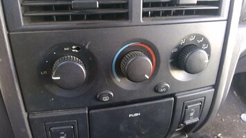
I thought about this when I noticed my '04 WJ has a separate AC switch,
Being that it's close in years, in might help to look how it's wired.

s-l1600.jpg
 
The switching path you tried to tie into is on the ground path, not the 12V path for the blower motor. The blower motor‘s 12V lead is direct. So, to get your switch to light up when the level switch is activated, wire one side of the switch’s light circuit directly to a switched 12V source and the other side to the DB/WT wire.
 
The switching path you tried to tie into is on the ground path, not the 12V path for the blower motor. The blower motor‘s 12V lead is direct. So, to get your switch to light up when the level switch is activated, wire one side of the switch’s light circuit directly to a switched 12V source and the other side to the DB/WT wire.

Oh that makes sense, I look forward to making another run at in the morning.