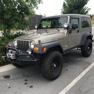
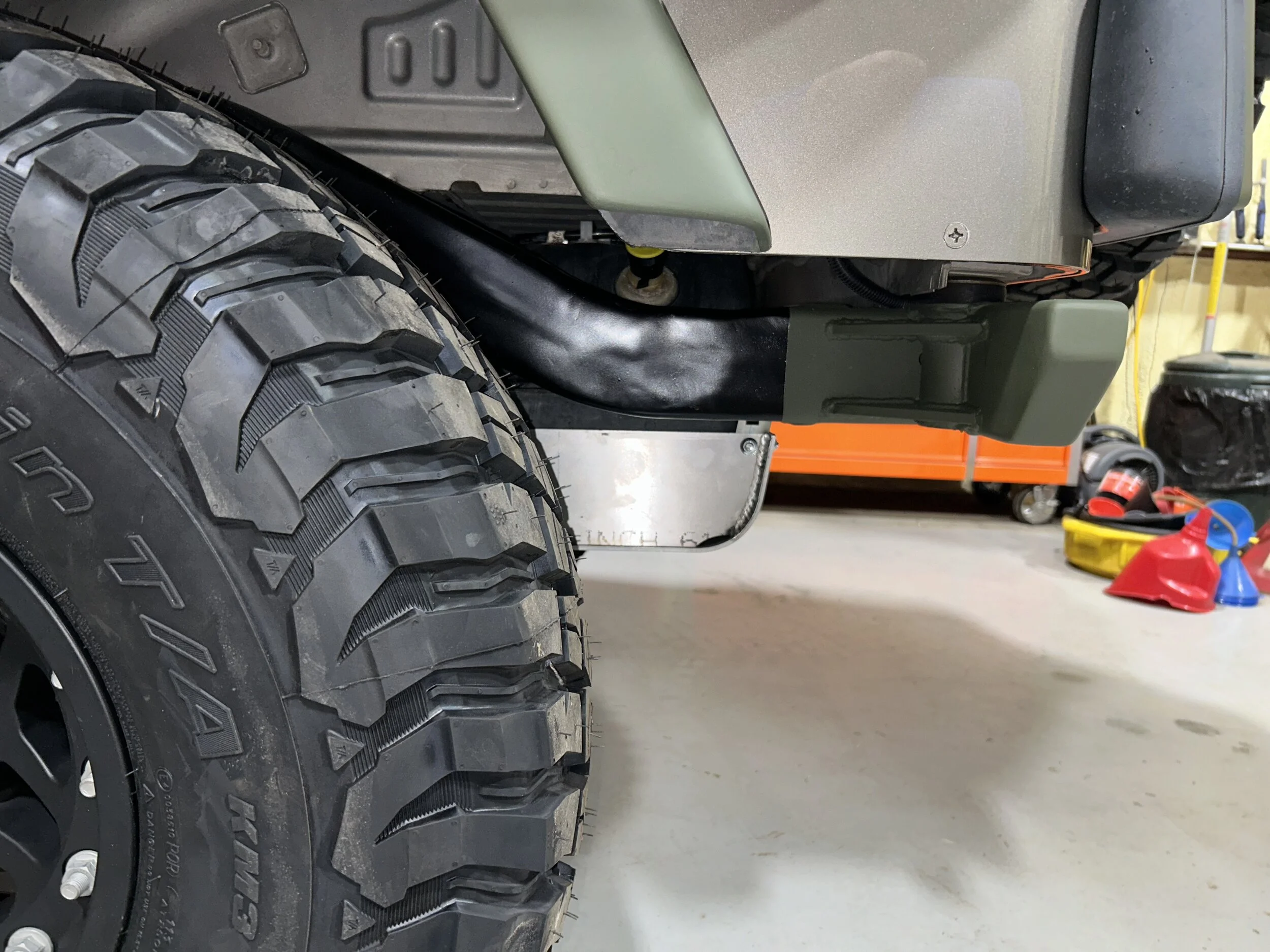
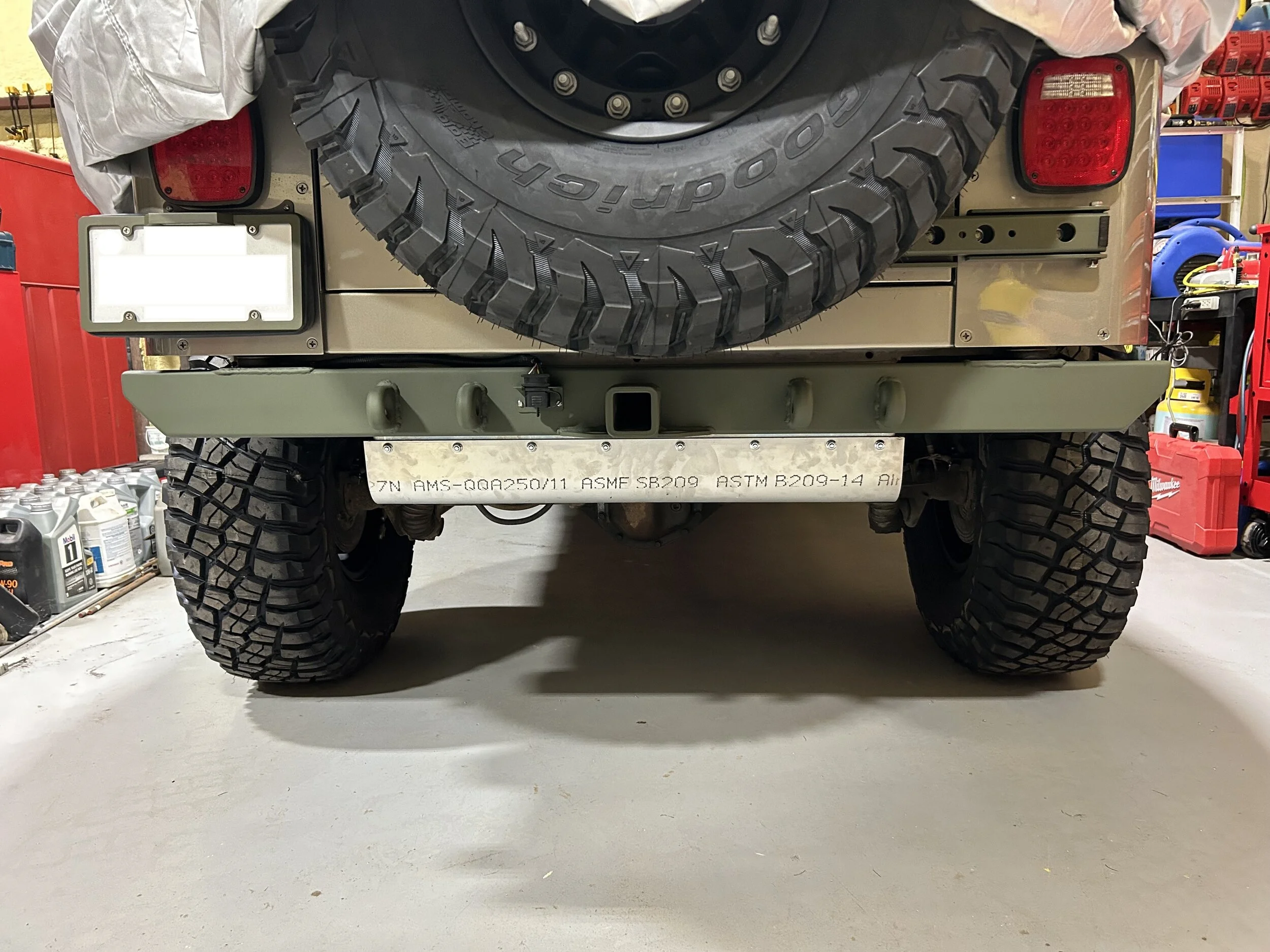
And here's the culmination of my rear frame raise project:
Next!
Next!


Thank you for doing that Mr. Blaine! That's a good lookin' flare!You asked about the double flaring tool somewhere. I did one with the K-tool version. I used the "fully annealed" crap from Inline Tube which if that is what fully annealed is, I want nothing to do with anything that isn't.
Here is the flare, 45 degree SAE, double flare. Cut with a cut-off disc, deburred on a sander, nothing that could contribute to work hardening and surprisingly, it came out perfectly acceptable.
View attachment 548568
View attachment 548569
Ignore the existing nutsert holes, just remove the nutserts. Do your lay-out mechanically and aesthetically paying attention to the length of your backer inside. Once they are laid out appropriately, drill through the clamped in place aluminum rail with a Rotabroach in 3/8" for 5/16" diameter fasteners at all locations. Don't try to hit the existing holes. They may be too high or too low and you don't want to compound an error.One other issue for which I seek guidance is how to deal with the fact that I've already installed nutserts for the step sliders in the area where the internal backing plates go below the door opening. Those nutserts will prevent the inner backing plates from sitting flat to the body. If I remove those and use the larger diameter holes left behind for mounting the step sliders (and add screws in between), I believe I'll be okay because it's the clamping force from bolt stretch that holds everything together (the body sandwiched between the inner and outer aluminum backers), rather than the edge of the body's hole. Thoughts?
Understood, but since I'm reinstalling the step sliders over the aluminum sliders, should I plug weld the existing step slider holes and drill new ones in order to avoid the old holes? I can likely use the buddy's mill to clean up the plug welds better than I did with the rear frame raise, since the griding on those wasn't even close to flat. Here's the sequence that this would entail:Ignore the existing nutsert holes, just remove the nutserts. Do your lay-out mechanically and aesthetically paying attention to the length of your backer inside. Once they are laid out appropriately, drill through the clamped in place aluminum rail with a Rotabroach in 3/8" for 5/16" diameter fasteners at all locations. Don't try to hit the existing holes. They may be too high or too low and you don't want to compound an error.
Just a bit of practice and you can use the sanding disc and then a couple more to get them to be flat. Milling sucks and you know that.Understood, but since I'm reinstalling the step sliders over the aluminum sliders, should I plug weld the existing step slider holes and drill new ones in order to avoid the old holes? I can likely use the buddy's mill to clean up the plug welds better than I did with the rear frame raise, since the griding on those wasn't even close to flat. Here's the sequence that this would entail:
- Plug weld the existing holes in the step sliders and mill them flat.
Yes
- Remove existing nutserts that were installed for the step sliders.
No
- Clamp aluminum outer and inner backers in place.
Rotabroach has a limited cutting depth. Somewhere around 3/8" or so.
- Drill 3/8" holes through aluminum outer backer, steel body, and aluminum inner backer in one operation (Rotabroach).
Countersink first. The countersink always guides the Rotabroach to the center, exact center of the hole.
- Remove backers and countersink on drill press.
Not enough info. But, hex bolts are going to look like shit. It is a simple matter to slightly oversize the top part of the hole in the aluminum even if you just kiss it with a countersink and then use flat heads for the step slider. Even button head Torx would look better.Complicated, I know. Is this the best plan?
- Install aluminum outer and inner backers.
- Clamp step slider in place.
- Drill 3/8" holes through steel step slider, aluminum outer backer, steel body, and aluminum inner backer in one operation (Rotabroach).
- Install step slider (I think it's 11 gauge, so I'll just use hex head bolts since it's thicker than the .191" thick heads on 5/16"-18 flathead screws).
I guess it's worth a try. I'm a better machinist than grinder (and all that does is say how bad a grinder I am), but they do say that practice makes perfectJust a bit of practice and you can use the sanding disc and then a couple more to get them to be flat. Milling sucks and you know that.

Crap. I was thinking that depth would be okay because I'm going through several layers, but as soon as I read that, I remembered that they are stepped, so that won't work. So the better plan is drill and countersink the aluminum first and use that hole as a guide to drill the body holes. That makes sense - it's what I did with the GR corners.Rotabroach has a limited cutting depth. Somewhere around 3/8" or so.
Agreed. My concern was whether or not a flathead would pull through 11ga steel under load, since the clamping force is resisted by the small countersink contact area:...hex bolts are going to look like shit.
Thank you for doing that Mr. Blaine! That's a good lookin' flare!
I'm building some SS hardlines for a build. After doing several, I can tell the tool isn't going to be long for this world. It does them, it really doesn't like it. I'll get done, but I'm pretty sure that when I am finished, the tool won't do another set. That is 5 flares so far.
There are several different brands on what appears to be the same tools. I do not know if there is a difference, I suspect there could be since knock-off levels of quality tend to vary.It's sad that there doesn't seem to be any real info out there on a proper tool to flare the annealed stainless tubing. I just called Inline Tube, and here's a record of my conversation with their tech rep:
Q: To your knowledge, has Inline Tube had any tubing batches released with improper annealing?
A: Not to my knowledge
Q: Have you had any complaints that your TLF08 flaring tool (looks exactly like the K-Tool tool) wears quickly when used on stainless tubing?
A: No, it's what we normally recommend
Well that's bullshit. Were there 2 flares per vehicles or 20? If there were 20, that guy is a brake line and flaring stud. Especially since they can not be done under the vehicle like you can do with the Mastercool. To get it correct, you have to snug down a fittings and restraints, mark the cut, disassemble, carry to the tool and then flare it. In perspective, I've done 100's upon 100's of flares including some stainless with my Mastercool and it works today exactly like it did the first day I used it with zero issues. I am also not concerned about the dies, they seem fine. What is showing wear is the lever press mechanism.Q: Are you aware of a better tool to flare stainless tubing?
A: We do have a hydraulic tool, part number TLF12 (My Note: That tool looks like a lighter-duty version of the MasterCool, so I'm not impressed). It's more expensive, but it, too, is recommended for stainless tubing.
Q: Have you had any complaints that your TLF12 hydraulic flaring tool wears quickly when used on stainless tubing?
A: Only one. I had a gentleman that did about 8 vehicles in one day, and wore out the dies.
I despise cupronickel. It is far too delicate for use in an offroad vehicle. If you want cupro-nickel, I'll send you what I have left since I'll never use it again.It seems like the K-tools is the best available tool, but you best plan on burning a set of dies with each vehicle done. Sad. Maybe the CuproNickel tubing is a better route?
If I was concerned, I'd add more fasteners. They can't be any worse than an undercut head which does the exact same thing and I've never had any issue with them. I am flailing about in the dark since I do not have a visual reference, just your description.Unrelated - regarding the last part of my last post on the sliders. Would you be concerned about flatheads pulling through the 11ga steel of the step sliders?
So, having used both the K-Tool and the MasterCool, would you recommend the MasterCool over the K-tool for stainless?In perspective, I've done 100's upon 100's of flares including some stainless with my Mastercool and it works today exactly like it did the first day I used it with zero issues. I am also not concerned about the dies, they seem fine. What is showing wear is the lever press mechanism.
Asked and answered (thank you!) - no need to send me that tubingI despise cupronickel. It is far too delicate for use in an offroad vehicle. If you want cupro-nickel, I'll send you what I have left since I'll never use it again.

I do plan to increase the number of fasteners (they fasten to the vertical body sides with only six screws). Besides the drawing I posted in Post 168 above, what pictures could I take and post later to help shed more light?If I was concerned, I'd add more fasteners. They can't be any worse than an undercut head which does the exact same thing and I've never had any issue with them. I am flailing about in the dark since I do not have a visual reference, just your description.
Not really. The MC dies have a larger gap between the pair so when you get it cranked down tight enough so the tube doesn't slip, it squeezes out two little ridges opposite each other. Then you have to turn the tube 90 degrees and reclamp it to mash the tube back into round or the tube nut won't slide down to the flare which also means if you don't get it close to perfect again, then you have to turn the flare nut with a tool to start it in the threads which is a disaster waiting to happen.So, having used both the K-Tool and the MasterCool, would you recommend the MasterCool over the K-tool for stainless?
I really don't mind, someone needs to use it up.Asked and answered (thank you!) - no need to send me that tubing
Pics of the parts might help.I do plan to increase the number of fasteners (they fasten to the vertical body sides with only six screws). Besides the drawing I posted in Post 168 above, what pictures could I take and post later to help shed more light?
Here are pictures of the step sliders - first by themselves, and then with the aluminum backers on the inside of them (Note: not shown - there are 3/16" steel outer armor pieces that bolt on to the outside of the step sliders, too):Pics of the parts might help.
Here are pictures of the step sliders - first by themselves, and then with the aluminum backers on the inside of them (Note: not shown - there are 3/16" steel outer armor pieces that bolt on to the outside of the step sliders, too):
View attachment 549554
View attachment 549555
View attachment 549556
View attachment 549558
View attachment 549559
View attachment 549560
View attachment 549561
For the vertical sides, I would use a lower row of seven screws, in a similar location as the screws that hold the steel Savvy sliders, along with two upper screws on ends, to attach the aluminum backers to the tub, and then an upper row of seven screws to attach both the step sliders and the aluminum backers. I stole the photo below of the Savvy sliders from a post made by someone else (thanks, @Midnight LJR!) and edited it to show what I'm thinking. The holes circled in red would go only through the aluminum backers, while the yellow ones would go through both the step sliders and the aluminum backers. As for the holes into the bottom of the tub, I've not gotten that far, yet.
View attachment 549580
By the way, there's very little info on the mechanical properties of those stainless Type F torx flathead decking screws you are using, but what information I can find looks like they are not high strength (meaning similar to alloy socket head cap screws). Are the ones you are using high strength?
View attachment 549557

It's been over a week since my last post, but that's not indicative of a lack of work on the step slider reinforcement project. Last week, during the forum's re-build, Mr. Blaine and I took the discussion to email. I had asked for his thoughts on how to combine his original Savvy slider design with the Rockslide Engineering step sliders for optimum protection. I think we've come up with a good way to do it. There are a few issues to deal with. First, the step sliders are 1/8" thick steel, and I have the optional armor for them, which is 3/16" steel. The top bolts in the side of the body have to go through the 1/8" section of the sliders, so I decided to go with 1/4-20 bolts there instead of 5/16-18 because the head height of the 1/4-20 bolts is just a hair over 1/8. I actually started discussing this in Post #168 (see the last CAD drawing I posted, which shows a 5/16-18 bolt through the 1/8" steel slider) before resorting to email with Mr. Blaine. I'm using 9 of those 1/4-20s since they'll not be as robust as the 5/16-18 bolts. In order to do that, I'll have to plug weld the old holes in the Rockslide sliders and drill new ones (more on that at the end of this post).
Another issue is at the bottom of the sliders. Mr. Blaine suggested putting long-reach nutserts in the aluminum backers and screwing through the Rockslide armor and sliders to the aluminum backers in the empty area between the outer body wall and the torque boxes and cutting the Rockslide sliders and armor short, since they would no longer be screwed into the torque box (only the aluminum backer will be screwed into the torque box). So, here's a cross section showing the plan:
View attachment 551790
Another issue is the bending load on the Rockslide sliders at the bottom. The gussets (shown hatched above) will be added to move the fulcrum point outboard. I'll weld those to the inside of the Rockslide sliders.
So, with a plan in mind, yesterday I started executing it in earnest. Here, I've drawn the cut line for Rockslide bottoms, and placed center marks for the bottom bolts:
View attachment 551792
After that, I masked the surface (this armor is already custom powder coated) and clamped on a straight edge for the circular saw offset from the cut line:
View attachment 551793
Next, I commenced to cuttin'. I cut through both the 1/8" slider and the 3/16" armor in one go. Here I am halfway through the first side:
View attachment 551794
One nice side benefit of cutting the Rockslide sliders off is the weight loss, which is not trivial:
View attachment 551795
That's equivalent to more than one of the aluminum backers! Here are the Rockslide sliders with the bottoms cut off:
View attachment 551796
That Milwaukee saw leaves a nice, clean cut, but the edges are very sharp. I used a coarse file, fine file, and some emery cloth to take the edge off:
View attachment 551799
Next, I drilled and countersunk the holes in the bottom. A Rotabroach in the mag-base drill made short work of it:
View attachment 551797
And nice and slow with the countersink made for chatter-free countersinks:
View attachment 551798
Finally, I started on the plug welds for the existing holes in the Rockslide sliders. First, I used the Wizard's expensive, magic wheel in my M18 drill to quickly remove the powder coating. That thing really is magic! Below, you can see a copper plug weld device on the underside, but it didn't work - the spring was too weak, and I ended up die-grinding and starting over:
View attachment 551800
I ended up using a big chunk of copper with some small C-clamps to do it proper-like:
View attachment 551801
And the result:
View attachment 551802
And that was it for the weekend's work. I have about a dozen more to plug weld, and then grind and dress them up, followed by drilling and countersinking the new holes. Stay tuned!
It's been over a week since my last post, but that's not indicative of a lack of work on the step slider reinforcement project. Last week, during the forum's re-build, Mr. Blaine and I took the discussion to email. I had asked for his thoughts on how to combine his original Savvy slider design with the Rockslide Engineering step sliders for optimum protection. I think we've come up with a good way to do it. There are a few issues to deal with. First, the step sliders are 1/8" thick steel, and I have the optional armor for them, which is 3/16" steel. The top bolts in the side of the body have to go through the 1/8" section of the sliders, so I decided to go with 1/4-20 bolts there instead of 5/16-18 because the head height of the 1/4-20 bolts is just a hair over 1/8. I actually started discussing this in Post #168 (see the last CAD drawing I posted, which shows a 5/16-18 bolt through the 1/8" steel slider) before resorting to email with Mr. Blaine. I'm using 9 of those 1/4-20s since they'll not be as robust as the 5/16-18 bolts. In order to do that, I'll have to plug weld the old holes in the Rockslide sliders and drill new ones (more on that at the end of this post).
Another issue is at the bottom of the sliders. Mr. Blaine suggested putting long-reach nutserts in the aluminum backers and screwing through the Rockslide armor and sliders to the aluminum backers in the empty area between the outer body wall and the torque boxes and cutting the Rockslide sliders and armor short, since they would no longer be screwed into the torque box (only the aluminum backer will be screwed into the torque box). So, here's a cross section showing the plan:
View attachment 551790
Another issue is the bending load on the Rockslide sliders at the bottom. The gussets (shown hatched above) will be added to move the fulcrum point outboard. I'll weld those to the inside of the Rockslide sliders.
So, with a plan in mind, yesterday I started executing it in earnest. Here, I've drawn the cut line for Rockslide bottoms, and placed center marks for the bottom bolts:
View attachment 551792
After that, I masked the surface (this armor is already custom powder coated) and clamped on a straight edge for the circular saw offset from the cut line:
View attachment 551793
Next, I commenced to cuttin'. I cut through both the 1/8" slider and the 3/16" armor in one go. Here I am halfway through the first side:
View attachment 551794
One nice side benefit of cutting the Rockslide sliders off is the weight loss, which is not trivial:
View attachment 551795
That's equivalent to more than one of the aluminum backers! Here are the Rockslide sliders with the bottoms cut off:
View attachment 551796
That Milwaukee saw leaves a nice, clean cut, but the edges are very sharp. I used a coarse file, fine file, and some emery cloth to take the edge off:
View attachment 551799
Next, I drilled and countersunk the holes in the bottom. A Rotabroach in the mag-base drill made short work of it:
View attachment 551797
And nice and slow with the countersink made for chatter-free countersinks:
View attachment 551798
Finally, I started on the plug welds for the existing holes in the Rockslide sliders. First, I used the Wizard's expensive, magic wheel in my M18 drill to quickly remove the powder coating. That thing really is magic! Below, you can see a copper plug weld device on the underside, but it didn't work - the spring was too weak, and I ended up die-grinding and starting over:
View attachment 551800
I ended up using a big chunk of copper with some small C-clamps to do it proper-like:
View attachment 551801
And the result:
View attachment 551802
And that was it for the weekend's work. I have about a dozen more to plug weld, and then grind and dress them up, followed by drilling and countersinking the new holes. Stay tuned!
I like how your integrating the powered step into something that might actually be able to take a hit.
Yes, when I bought the steps, I hadn't yet discovered all the forum posts about sliders. That was almost three years ago. Once I realized the shortcomings, I decided to rectify it because I really like having the steps as I go into "the golden years" with my LJ. I had been trying to purchase the Savvy aluminum slider backers for years, but they just wouldn't (couldn't?) make a batch of them. One day, I was talking to Mr. Blaine, and then jjvw, about how to properly build some myself, when Mr. Blaine told me that Fluxor was going to be making some. He put in a word to Fluxor for me, and I was able to buy a set sans holes from him, which worked out perfectly!Like @Mike_H said .. you will have a functional (in terms of protection) set of powered steps. Thanks for taking the time to do the photos and the write ups.
Absolutely, there are decades of experience and sound engineering into Mr. Blaine's original designs, and I'm extremely appreciative to be able to short-cut the trial-and-error phase for my build! This forum, and the resources available on it, are a huge blessing to TJ owners.