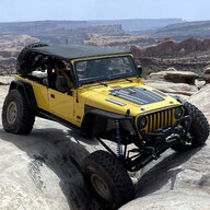
Wildman's TJ is getting a face lift

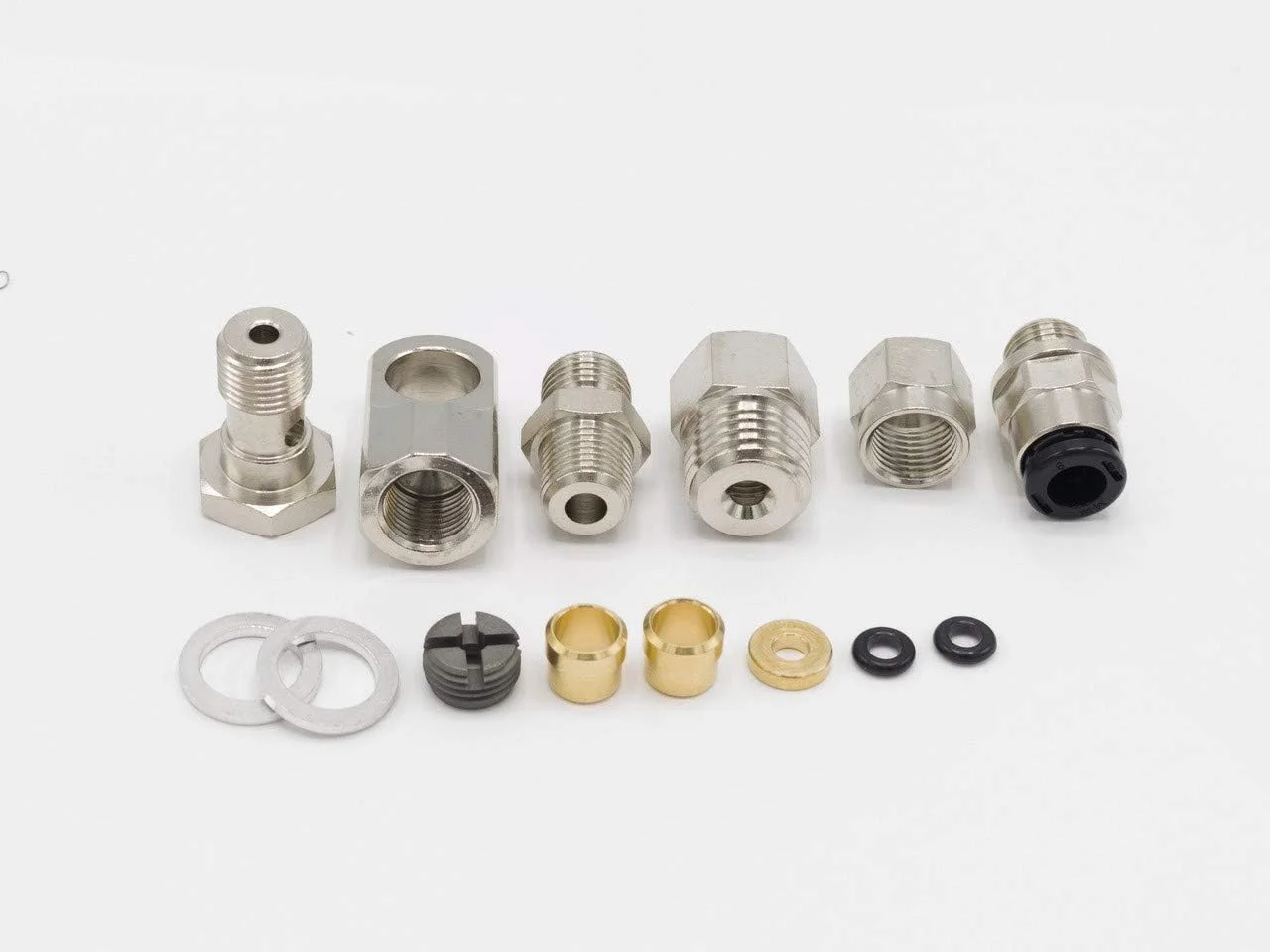
With the design of the truss I needed a ARB bulkhead fitting kit... And of course I can't get one with 2nd day delivery. Won't be here until next Monday...
But I can get all the other things done on the Jeep while I'm waiting...

1785951532773.webp


The truss has a hole for the ARB air ling in the rear of it which I'll use with the push connector. Thought I had one already but can't find it so I ordered a new kit.
 
Here's the hole in the rear of the new truss for the air line to go through....

20260805_151345.webp


20260805_151351.webp


The ARB fitting is approx here under the truss.

20260805_151402.webp


So I could drill a hole like in the previous truss and run the air line to the current fitting

20260805_151409.webp


But honestly I like the push connector more... My only concern is that once I've got it installed if something was to fail there isn't any way to reach it once the truss is welded on.... Other than by either drilling a larger hole around where my finger is or cutting a square hole in that location to gain access....
Now the chances of the bulkhead fitting failing or having issues are slim to none...

Going to have to think on this one for a while...
 
Here's the hole in the rear of the new truss for the air line to go through....

View attachment 703040

View attachment 703041

The ARB fitting is approx here under the truss.

View attachment 703042

So I could drill a hole like in the previous truss and run the air line to the current fitting

View attachment 703043

But honestly I like the push connector more... My only concern is that once I've got it installed if something was to fail there isn't any way to reach it once the truss is welded on.... Other than by either drilling a larger hole around where my finger is or cutting a square hole in that location to gain access....
Now the chances of the bulkhead fitting failing or having issues are slim to none...

Going to have to think on this one for a while...

I have not had good luck with the push-on air connectors. They sealed fine at first, but then developed leaks. I switched most of them out for old skool compression sleeves and ferrules. I have 3 left to do, that I'll take care of next time I'm in where they are.
 
I have not had good luck with the push-on air connectors. They sealed fine at first, but then developed leaks. I switched most of them out for old skool compression sleeves and ferrules. I have 3 left to do, that I'll take care of next time I'm in where they are.

I've got the push connectors all over my Jeep with the AiRock and have good luck with them... The ARB one on the rear axle is still working as it should... But if push comes to shove I can always go back to the old style sleeve & ferrule.

On a side note: I found my front axle u-joint strap bolts loose when I was removing the front driveshaft. Not sure what happened since they were new bolts with lock-tite on them too...
But I ordered new straps and bolts just to make sure... When I'd had that axle geared I couldn't find a Dana 44 1350 u-bolt yoke anywhere at the time unfortunately so I had to run straps instead...

Played with the truss some more today and think I've got a plan of action for installing it. Got to fix my air compressor tomorrow so I can use my air hammer to peen the welds when I'm doing the steel to cast welds.
 
I've got the push connectors all over my Jeep with the AiRock and have good luck with them... The ARB one on the rear axle is still working as it should... But if push comes to shove I can always go back to the old style sleeve & ferrule.
Yea, that's what I did - but Hell, I dunno what went wrong. Particular brand of plastic air line? I'm an idiot? Who knows. *SHRUG*
 
Yea, that's what I did - but Hell, I dunno what went wrong. Particular brand of plastic air line? I'm an idiot? Who knows. *SHRUG*

This is the new 6mm line. And I'm using the ARB line for my lockers.

I had issues with some of the air line I'd started with for the AiRock & stuff but I figured out that I'd chosen the wrong air line and have replaced all of it. Since then no more issues..
 
Here's the hole in the rear of the new truss for the air line to go through....

View attachment 703040

View attachment 703041

The ARB fitting is approx here under the truss.

View attachment 703042

So I could drill a hole like in the previous truss and run the air line to the current fitting

View attachment 703043

But honestly I like the push connector more... My only concern is that once I've got it installed if something was to fail there isn't any way to reach it once the truss is welded on.... Other than by either drilling a larger hole around where my finger is or cutting a square hole in that location to gain access....
Now the chances of the bulkhead fitting failing or having issues are slim to none...

Going to have to think on this one for a while...

Don't think about how you will install and remove the line - that's not the driiver for how you need to access it. Think about how you will install and remove the entire fitting assembly when you have to do so - that's the driver for the access decision.
 
This is the new 6mm line. And I'm using the ARB line for my lockers.

I had issues with some of the air line I'd started with for the AiRock & stuff but I figured out that I'd chosen the wrong air line and have replaced all of it. Since then no more issues..

There's a real message there!
 
  • Like
Reactions: John Cooper
Don't think about how you will install and remove the line - that's not the driiver for how you need to access it. Think about how you will install and remove the entire fitting assembly when you have to do so - that's the driver for the access decision.

And I've been going over that in my head & trying to come up with a way that won't impact the structural integrity of the truss. Maybe make a access hole and then bolt a cover over it? I'm open to ideas or suggestions....

Even if I use the sleeve and ferrule style I've still got to have a hole there...
 
Good news is that the bulkhead fitting kit will be here tomorrow afternoon instead of Monday...... So it'll give me some extra time to get the truss installed.

Back before the Jeep had broke I'd entered it in the Kittitas Car Show & Burnouts

1786039280027.webp


https://www.kittitascountychamber.com/kruisin-kittitas/

Of course if it's not ready I won't go but I'm hoping I can make it.
 
How about cutting a hole in the truss for access...then adding plate around the hole and welding in some scrap DOM tube...not all the way to the axle...but a 1/4 or 1/2 inch or something.

-Mac

This was something I'd been thinking about but wasn't sure how much it would help... I was thinking about a large washer maybe with the center opened up some & drill some holes around it so I could plug weld it.
But still looking at options & ideas... Once I have the fitting kit I can see how much room I'll need....
 
And I've been going over that in my head & trying to come up with a way that won't impact the structural integrity of the truss. Maybe make a access hole and then bolt a cover over it? I'm open to ideas or suggestions....

Even if I use the sleeve and ferrule style I've still got to have a hole there...

I think you are over thinking it. A hole in that location just large enough to access the fitting will not appreciably impact the structural integrity of the truss enough to matter.

But you know who would know: @sab

Mine has holes all over it to reduce weight:

IMG_2021.webp


Although on mine, I did not have to go through the truss to access the ARB fitting:

IMG_2023.webp
 
I think you are over thinking it. A hole in that location just large enough to access the fitting will not appreciably impact the structural integrity of the truss enough to matter.

But you know who would know: @sab

Mine has holes all over it to reduce weight:

View attachment 703192

Although on mine, I did not have to go through the truss to access the ARB fitting:

View attachment 703197

This hole isn't large enough to access the fitting if I was going to install or remove it...

20260805_151351.webp


In my mind what I'd need to do is put a hole about where my finger is large enough to install or remove the fitting.

20260805_151402.webp


And yes I'm probably being a little gun shy now since I'd ripped the last one off so I'm wanting to over build/enforce this truss. I could have done a TON more damage if I hadn't stopped when I did. I could of ripped the air springs and/or bent the shocks.
That upper 3 link puts some serious forces on the truss... And with the Ford HP44 I don't have the threaded mounts in the casting like you do.

I'll totally agree I might be over thinking this....
@sab what say you sir?
 
Holes, strategically placed, can be added to most parts with little effect on durability. In fact, it's done all the time to reduce weight (yes, that's my favorite subject). I did it in my build with Fluxor's tire carrier, which was too heavy for my taste. The basic idea is to not have sharp changes (which we engineering-types call "stress concentrations") in how forces are distributed internally in an object under load. SendCutSend has a good basic explanation here. Take the most simple example of a hole in a part under tension:
1786054236179.webp


The bigger you make the hole, or the closer you get to the edges, the closer those red lines get to each other, and stress is directly proportional to the closeness.

However, in the case of an axle, the force distribution is not only complex, but it's dynamic (changing all the time). It's not so obvious to visualize those red lines. In this case, you have to just make an educated guess, or you have to do an engineering analysis to better visualize the red lines. In this case, I'm advocating for the educated guess method, since I don't have time to do any analysis.

You should use these factors to determine where to put the hole, and how it should be shaped:
  1. Keep the hole(s) as close to the geographic center of whatever face it's on.
  2. Keep the hole(s) as small as possible.
  3. It's okay, and sometimes preferable, to make the hole something other than a circle. Sure, it's harder to make the hole that way because you can't simply drill or use a hole saw, but offsetting from the outside edges is a good way to do it - usually. Like this (parden the shakiness - using a mouse):
    1786055204474.webp
  4. Don't put any sharp corners in the holes. If you use holes like above, use the largest radius you can at each corner.
  5. Stay away from other stress concentrations. For example, in your last picture in Post #15,014, you have two stress concentrations close to where you're pointing: The bend radius of that piece, and the witness mark from the press brake knife just under your finger. Both of those have a double-whammy on stress in that area: first, they cause forces to be concentrated, as just mentioned, but second, the forming has work-hardened the material, which makes it stronger, but more brittle. In a part subject to dynamic loading, work hardening and brittleness is not good because cyclic stresses cause fatigue failures. Regarding the press brake knife witness mark, I've seen those cause a failure. They seem like just a cosmetic defect, and 99% of the time that's all they are. Stay away from them, and that 99% goes to 100%.
  6. Don't create a bunch of small stress concentrations by leaving a very rough cut line. Use a file to smooth things up if you need to. A bunch of small, jagged bumps can add up to a significant stress concentration. I spent a LONG time cleaning up my cuts in that tire carrier for this reason (and I still wasn't satisified with it, but it's stainless and very hard to file.) It's also why I love having parts laser cut! Side note: even with laser-cut parts, I have a bit of edge clean-up. There's always a "tag" left somewhere on each perimeter. It's there because they need the cut parts to stay put and not move around while the toolhead is still traversing the workpiece. If not, the toolhead hits a loose part, and now the laser alignment is screwed up, or worse - the machine breaks. It's ever so small - just large enough to hold the entire workpiece together, but small enough to twist and break the cut parts off the workpiece. I still file them off unless I KNOW they won't be a crack instigation point!
All that said, I always look to Mr. Blaine's work for cues because he not only understands these things (many times better than I do), but he also understands the loading parts see, and how things break. I understand the engineering concepts, but I am out of my element with TJ axles and suspension. My LJ is the first vehicle I've worked on with solid axles, so his expertise and genius-level solutions are always my first stop when approaching design of a part for the LJ. Look at his mid-arm truss (picture credit here):
1786055933496.webp


See how inconsequential those vertical faces are? That tells me that those faces don't see much stress, so that's where I'd put the hole(s) for access. You should be able to do something like this to one or both sides of those vertical faces and get in there with a combination wrench (maybe with a flex-head?) and your cigar-stained digits to remove/replace the fitting:
1786056381350.webp


Let me know if I've glossed over anything, and I'll clarify.
 
Holes, strategically placed, can be added to most parts with little effect on durability. In fact, it's done all the time to reduce weight (yes, that's my favorite subject). I did it in my build with Fluxor's tire carrier, which was too heavy for my taste. The basic idea is to not have sharp changes (which we engineering-types call "stress concentrations") in how forces are distributed internally in an object under load. SendCutSend has a good basic explanation here. Take the most simple example of a hole in a part under tension:
View attachment 703235

The bigger you make the hole, or the closer you get to the edges, the closer those red lines get to each other, and stress is directly proportional to the closeness.

However, in the case of an axle, the force distribution is not only complex, but it's dynamic (changing all the time). It's not so obvious to visualize those red lines. In this case, you have to just make an educated guess, or you have to do an engineering analysis to better visualize the red lines. In this case, I'm advocating for the educated guess method, since I don't have time to do any analysis.

You should use these factors to determine where to put the hole, and how it should be shaped:
  1. Keep the hole(s) as close to the geographic center of whatever face it's on.
  2. Keep the hole(s) as small as possible.
  3. It's okay, and sometimes preferable, to make the hole something other than a circle. Sure, it's harder to make the hole that way because you can't simply drill or use a hole saw, but offsetting from the outside edges is a good way to do it - usually. Like this (parden the shakiness - using a mouse):View attachment 703238
  4. Don't put any sharp corners in the holes. If you use holes like above, use the largest radius you can at each corner.
  5. Stay away from other stress concentrations. For example, in your last picture in Post #15,014, you have two stress concentrations close to where you're pointing: The bend radius of that piece, and the witness mark from the press brake knife just under your finger. Both of those have a double-whammy on stress in that area: first, they cause forces to be concentrated, as just mentioned, but second, the forming has work-hardened the material, which makes it stronger, but more brittle. In a part subject to dynamic loading, work hardening and brittleness is not good because cyclic stresses cause fatigue failures. Regarding the press brake knife witness mark, I've seen those cause a failure. They seem like just a cosmetic defect, and 99% of the time that's all they are. Stay away from them, and that 99% goes to 100%.
  6. Don't create a bunch of small stress concentrations by leaving a very rough cut line. Use a file to smooth things up if you need to. A bunch of small, jagged bumps can add up to a significant stress concentration. I spent a LONG time cleaning up my cuts in that tire carrier for this reason (and I still wasn't satisified with it, but it's stainless and very hard to file.) It's also why I love having parts laser cut! Side note: even with laser-cut parts, I have a bit of edge clean-up. There's always a "tag" left somewhere on each perimeter. It's there because they need the cut parts to stay put and not move around while the toolhead is still traversing the workpiece. If not, the toolhead hits a loose part, and now the laser alignment is screwed up, or worse - the machine breaks. It's ever so small - just large enough to hold the entire workpiece together, but small enough to twist and break the cut parts off the workpiece. I still file them off unless I KNOW they won't be a crack instigation point!
All that said, I always look to Mr. Blaine's work for cues because he not only understands these things (many times better than I do), but he also understands the loading parts see, and how things break. I understand the engineering concepts, but I am out of my element with TJ axles and suspension. My LJ is the first vehicle I've worked on with solid axles, so his expertise and genius-level solutions are always my first stop when approaching design of a part for the LJ. Look at his mid-arm truss (picture credit here):
View attachment 703240

See how inconsequential those vertical faces are? That tells me that those faces don't see much stress, so that's where I'd put the hole(s) for access. You should be able to do something like this to one or both sides of those vertical faces and get in there with a combination wrench (maybe with a flex-head?) and your cigar-stained digits to remove/replace the fitting:
View attachment 703243

Let me know if I've glossed over anything, and I'll clarify.

Thanks this helps a lot... And gives some ideas on maybe how to attack this now... I think enlarging the hole in the rear similar to how you have it drawn plus maybe a round hole in the front would give me all the access I need to get at the fitting. I don't know that I'd need to cut out the rear face as much as you have drawn but again won't know until I have it all sitting here in front of me. But tomorrow I can start playing with it more and see what I need room wise to access it.
 
Well like always when I want/need something to arrive when they say it's going to be delivered it always seems to not be...
UPS said originally that it'd be here NLT 2PM but now I'm seeing it's been changed to NLT 9PM.

But I worked on the front & rear plates and think I've got the access hole large enough to work on the ARB fitting.

Here's the enlarged hole in the rear plate...

20260807_153016.webp


And I added a hole in the front plate to facilitate working on the fitting.

20260807_153029.webp


Drained the gear oil out of the diff and then cleaned it up.

20260807_153124.webp


Sitting on the axle now.
Front view

20260807_153901.webp


20260807_153905.webp


Rear view

20260807_153933.webp


20260807_153939.webp


So I'll tackle the truss and fitting tomorrow now.
 
OK back to the drawing boards here....
Question for @sab or others please... With the way the new ARB bulkhead fitting is setup you install an 0-ring then washer then another 0-ring then a screw in compression nut. And to be able to screw in that compression nut the only way I can figure it out is to put a small 3/8"-7/16" hole over the ARB fitting. But that will make it close to the break in the truss... About where my finger is pointing. I'd make the hole as small as possible. It just needs to be large enough for a small screwdriver to fit through.

1786233484092.webp


So what can I get away with here? And if I put a hole here do I need to reenforce it too?

20260805_151402.webp


I've tried a few different ways to install it and am coming up busted..
 
This is a cool design on a truck with a cantilever setup & airbag.

View attachment 703522

Cantilever suspensions fascinate me. I've seen some videos of some pretty cool systems on off-road vehicles and Jeeps. Whether it's better or not is beyond my current level of understanding. But definitely has a cool factor.