I would have put the diode on the trigger wire, but if it works, it works! Glad you got it...
hmmm ... if by trigger wire you mean the power to the relay, then it is. I have a EE friend and he confirmed the wiring.
I would have put the diode on the trigger wire, but if it works, it works! Glad you got it...
That's called a "Snubber Diode", and is the correct way to deal with this problem. It effectively shorts out the inductive kickback from the solenoid coil when it de-energizes. And good on you for using a solenoid - far safer to keep all that wiring de-energized when not in use. A lifetime designing high energy DC systems taught me that.
hmmm ... if by trigger wire you mean the power to the relay, then it is. I have a EE friend and he confirmed the wiring.
View attachment 400598
I wouldn't have guessed that it was the coil circuit causing the issues. I would have suspected that it was the shunting of the primary circuit causing the voltage spike (through the secondary/coil circuit and into the switch). In that instance, I would have thought the snubber diodes would be better installed parallel with the load (in this case, across the primary circuit terminals).
I wonder if the 12V+ wires to the battery/winch were removed would the switch still be having a problem? This is why I would have (and have done in the past) installed a diode on the coil trigger wire. Interesting and certainly good to remember!
That's called a "Snubber Diode", and is the correct way to deal with this problem. It effectively shorts out the inductive kickback from the solenoid coil when it de-energizes. And good on you for using a solenoid - far safer to keep all that wiring de-energized when not in use. A lifetime designing high energy DC systems taught me that.
This here but I have always heard it referred to as a shunting diode. Very common on air conditioning clutches and also Eaton Elockers.

I wouldn't have guessed that it was the coil circuit causing the issues. I would have suspected that it was the shunting of the primary circuit causing the voltage spike (through the secondary/coil circuit and into the switch). In that instance, I would have thought the snubber diodes would be better installed parallel with the load (in this case, across the primary circuit terminals).
I wonder if the 12V+ wires to the battery/winch were removed would the switch still be having a problem? This is why I would have (and have done in the past) installed a diode on the coil trigger wire. Interesting and certainly good to remember!

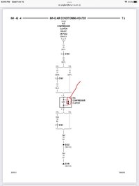
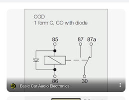
That is installed correctly, when the switch is turned off the voltage spike from the coil looks for a place to go and the led in the switch to ground was the path. The diode allows the ground to dissipate the voltage. Here is a relay diagram with a internal diode and the A/C clutch on a TJ.
Let's see if I can explain this in a comprehensible manner - if I don't succeed, someone else will probably explain it better than I can.Oh maybe I misidentified what the OP used - is that a TVS diode? His diagram showed a one-way (rectifier) diode, which is why I was surprised it worked (since the way it was orientated, it appears to allow voltage to travel back to the switch).
Oh maybe I misidentified what the OP used - is that a TVS diode? His diagram showed a one-way (rectifier) diode, which is why I was surprised it worked (since the way it was orientated, it appears to allow voltage to travel back to the switch).
I'm familiar with TVS's in a/c circuits and usually see them in this configuration (which is similar to OPs, except his is a rectifier diode):
View attachment 400797
I've always liked electrical stuff and sometimes wish I went down that career path... I know just enough to be dangerous, wire EFI, and add 220V circuits to the garage without worry
Let's see if I can explain this in a comprehensible manner - if I don't succeed, someone else will probably explain it better than I can.
When the solenoid coil is de-energized, the collapsing magnetic field induces a reverse polarity current ("Back EMF"), so the coil terminal that's connected to ground is suddenly positive. The diode then can short out this current to the circuit end (now negative), which suppresses a (reverse) current surge back up the wire. Without the diode, the current has to go *somewhere* - or perhaps better stated WILL go where-ever it can if it can find a path. I hope this makes sense...
I'm actually glad this came up, as I have a similar setup and I didn't think to put a snubber diode on it. Haven't blown the LED yet, but its probably only a matter of time. I have some 1N400x diodes here, I'll put one on!
I get all that - so why doesn't current flow back to the switch? Is it just that the diode is acting as more of a one-way resistor, slowing the surge of voltage? Or perhaps is it due to the difference between electron-flow and (conventional) current-flow (where the positive side of the coil circuit, now negative, is the electron source and then travels to ground, now positive)?
View attachment 400999
I've never seen a fuse on a winch before? Do they even have 500a fuses for this?
I've never seen a fuse on a winch before? Do they even have 500a fuses for this?
I use a 400A fuse. This will work for short duration loads at the highest draw (488A). I want it to pop before I achieve a long duration max load. You can get ANL fuses up to 750A.
Read the owners manual for your battery. Side terminals are not designed for high current loads. I run my starter off the side terminals and the winch on the top posts.
Some side posts are, like Odyssey. Some others, like Optima, aren't.Side terminals are not designed for high current loads. I run my starter off the side terminals and the winch on the top posts.

