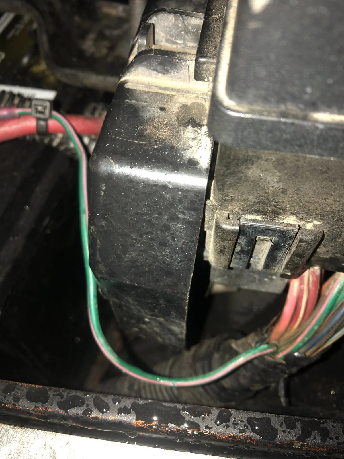
Where should this wire go?

Jmr17320

TJ Enthusiast
Original poster
Supporting Member
Joined
Jan 30, 2019
Messages
179
Location
Gettysburg PA
PO monkeyed with the wiring and ran this green/pink stripe wire to a circuit board. I want to remove all the extra wiring and want to put this back where it should go. It comes up with the main feed at the PDC. I think the PDC but I don’t see a short wire that would indicate such.

any ideas?
AF14A0C5-9EF3-4684-A221-E9B4FD3BE321.webp
 
PO monkeyed with the wiring and ran this green/pink stripe wire to a circuit board. I want to remove all the extra wiring and want to put this back where it should go. It comes up with the main feed at the PDC. I think the PDC but I don’t see a short wire that would indicate such.

any ideas?

View attachment 223357
Are you saying that the PO added this wire or pulled it out of the loom and rerouted it? I believe that DG/PK is Power to PCM from ASD relay. If your Jeep starts and runs now you'll want to consider the risk involved. That wire should run along the fender to the firewall and then to the PCM. It's possible that it shorted previously and the easy fix was to remove it from the loom and splice rather than adding a new section of wire with the original routing.
 
It runs inside the loom and terminates at the PDC. I really believe it should connect to the PDC. I guess I need to pull the top half of the PDC off and look underneath
 
FWIW I searched 8w-10 for 'DG/PK" and it looks like the only one going to the PDC is for your ASD relay. I don't know why the PO would have run that elsewhere, remote start maybe? Someone else might chime in that knows more.

1612448336261.webp

1612448404920.webp
 
What is ASD relay output sense?
Pretty sure PO did this as a safety so the electric fan switch was also turned on. I know if I disconnect, it will not start
 
So it looks like you have 3 of those DG/PK wires going to the PDC. One comes out of the ASD relay into a 3 way splice. From there one leg goes directly to the PCD, one leg goes back through fuse 18 in the PDC to the o2 sensors, and the third goes back through fuse 27 and off to your coil & injectors.

My best guess is that the circuit board you're talking about (got a pic?) is an o2 sensor repeater, but I could be way off. Of those 3 legs that would be the most likely explanation to me. Do you have a rear O2 sensor installed?

Edit: Nevermind about the o2 sensor idea, I saw that you said it was wire to the electric fan controller.

1612452025854.png


1612452057833.png
 
Last edited:
Update
I pulled the battery
Pulled all the fuses, relays
Tested all the PCM pins for continuity with the line wire (DG/PK)

it is gray connector pin 12, so where should it go at the PDC?

here is the circuit board I mentioned, for the 4 toggle switches inside the cab (e fan, e locker, fog, 4th is a mystery)

05DD9FC5-EAB1-4527-B40A-47C5CD5B3C9D.webp
 
If I am looking at this correctly,
I verified I have a DG/PK wire to fuse 18 and fuse 27.

bank B2 is empty for ASD relay.
So I should be able to install it back into that slot?
 
Whoa. You have quite a lot going on there.

Yes, that DG/PK wire is for B2 on the ASD relay.
 
Update

put wire back into PDC as mentioned and everything is good.

thanks to all who helped
What was the problem you were trying to solve anyway?
 
No, I meant it. The relays laid out nicely, organized. I would have dressed up the wiring a bit more but that's just me.
 
The problem I was trying to solve was several

1. undo all the wiring mods the PO did
2. I was having strange CEL issues and I suspected the PO wiring as the cause.