Solid round bar versus round tube

mrblaine

Crew Member
Original poster
Supporting Member
Joined
Nov 20, 2015
Messages
33,675
Location
Quail Valley, CA
This seems to generally be a confusing issue for folks to wrap their head around. There are some calculators out there that help figure some rough parameters for material selection but they can also be used to compare the different strengths of similar shapes in solid and tubular. This one is easy for me to use so I work with it from time to time to figure out some of the basics.

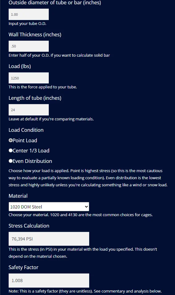
What you want to do is pick your material and size and then start changing the load number until you get the safety factor to 1.00 or as close to that as you feel like messing with.
I picked 1" solid bar to start. You can read the comments but when you get the safety factor to 1.00, that is the load the bar will hold before failing in a static condition.
1702650866758.png


So here is where it gets interesting and why some things matter and while on the face a statement may be true, the difference is actually negligible to the point where it may be readily ignored and not be factored into one's decision making process.

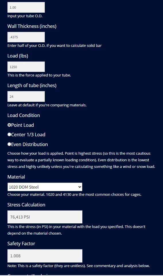
If we take the solid bar and reduce the wall thickness to .4375 to create a 1" diameter tube with a 1/8" hole through it, watch the safety factor, it doesn't change.
1702651356920.png


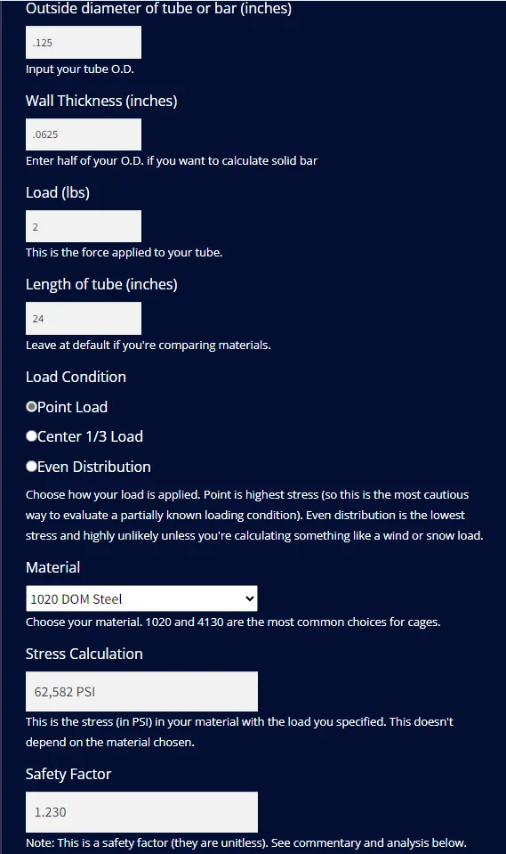
The reason it doesn't change much or enough to matter is the strength of a tube over solid is reduced by how strong or resistance to being bent as what it would take to bend the rod that was removed or in this case, a 1/8" diameter rod. The rod strength would be better to figure out if the force box allowed loads with a decimal as in 1.5 but it doesn't so the safety factor toggles back and forth between good and not good with 2 and 3 lbs of force applied. That's also why the safety factor didn't change enough above to show up.
1702651940894.png

Caveats- This is just a rough way to figure out the questions to ask about something. Something like a greasable bolt with a small hole drilled in it for a grease path. Most of the time the question asked is whether or not it is weaker and that answer is always yes with all other things being equal. The better question is whether or not it is weaker by enough to matter and in most circumstances, the answer is no. Or, even better, is it strong enough to do the job and that answer is mostly yes.

Early on in the TJ model run, lots of folks were complaining about why Jeep moved to the much weaker 5 on 4.5" bolt circle to hold on the wheels when the 5 on 5.5" version is so much stronger. The simple answer is the smaller pattern is more than strong enough so it doesn't matter.

A materials engineer can make a case that there is some strength picked up by having an inner and outer wall. I'm not that smart so they will have to explain it. I am aware that gun drilled axle shafts tend to work a fair bit better since they are more rotationally forgiving and tend to twist further and spring back more than a solid shaft will with no permanent damage. There is a whole bunch more to it than that, but it does work and the reason we don't see many GD shafts is we don't need them enough to justify the expense.

Rogue Fab has the calculator on their site.

Check my work and see if I screwed it up some place. I use this to figure out control arm diameters when needed compared to the lengths we need. Helps me pick between solid and tubular in steel versus aluminum. I hope it will be helpful for other discussions.
 
The calculator is calculating tensile stress in the outer fibers due to bending. That is why removing the center material has minimal effect (distance is squared). For a control arm, it would take a point load if it is against a rock but typically would be a two force member taking axial loads, so the axial load in addition to the bending load has to be accounted for.
 
I am aware that gun drilled axle shafts tend to work a fair bit better since they are more rotationally forgiving and tend to twist further and spring back more than a solid shaft will with no permanent damage.

Thanks Blaine , Good read and quite interesting. The Gun Drilled axles are what came to mind immediately , however It actually applies for a different reason
I guess. It makes sense for high end axles to have a little torsional " spring " to them .
 
The calculator is calculating tensile stress in the outer fibers due to bending. That is why removing the center material has minimal effect (distance is squared). For a control arm, it would take a point load if it is against a rock but typically would be a two force member taking axial loads, so the axial load in addition to the bending load has to be accounted for.

For those not immediately familiar with what an axial load is, you'll need to lay it out in plain English.

But, this isn't just for control arms.
 
Thanks Blaine , Good read and quite interesting. The Gun Drilled axles are what came to mind immediately , however It actually applies for a different reason
I guess. It makes sense for high end axles to have a little torsional " spring " to them .
All axle shafts have torsional spring to them. It is very common for folks to look at a wobbling rear axle shaft flange and tell everyone they bent the flange. That is actually very difficult to do. What is almost always the case, is the shaft has been rotated or twisted past the limit where it will spring back. Why that matters is almost all shafts come out of heat treat and the splines do not run concentrically to the flange. So, they put them on a straightener that has a dial indicator on the flange and turn it. There is a press that can be moved back and forth and the operator moves and mashes the shaft down in spots until the flange runs true to the splines with less than .005" run-out. Or at least that is the spec that Foote Axle used.

They don't care and it doesn't matter much that the shaft is straight, what matters is the splines run true to the flange and the bearing journal right inside the flange. When you over-rotate a shaft past its elastic limit, it usually winds up back to the post heat treat condition where the flange now wobbles out of true but the flange isn't bent.
 
The point load in the calculator is a load that is applied perpendicular to the rod mid way between the attach points. This load tries to bend the rod and places one side in tension and one side in compression. The axial load is a load applied through the end and straight down the rod (eg; load coming through the joint from weight of jeep or rod resisting the torque of axle). It would put the rod in tension or compression. This tension or compression would be the normal load on the control arm.

Yes, I agree. Good info and it applies to other applications. Not disagreeing, just trying to add to conversation.
 
The point load in the calculator is a load that is applied perpendicular to the rod mid way between the attach points. This load tries to bend the rod and places one side in tension and one side in compression. The axial load is a load applied through the end and straight down the rod (eg; load coming through the joint from weight of jeep or rod resisting the torque of axle). It would put the rod in tension or compression. This tension or compression would be the normal load on the control arm.

Yes, I agree. Good info and it applies to other applications. Not disagreeing, just trying to add to conversation.

I probably should have kept the control arm aspect out of it but, we almost never see a bent arm due to axial loads. We see a missed line, arm lands on a rock closer to the frame mount than the axle side with the tire in the air. Depending on the chassis angle at the 4 corners and what the other side is doing, the spring trying to extend places small to very high loads on that fulcrum and the arm suffers.
 
Taking control arms out and just speaking in general. I wonder how much is fatigue taken into account by aftermarket designer? Most of the cracks and eventual failures that I have come across on my jeep is due to fatigue and not due to single overload.
 
  • Like
Reactions: psrivats
Taking control arms out and just speaking in general. I wonder how much is fatigue taken into account by aftermarket designer? Most of the cracks and eventual failures that I have come across on my jeep is due to fatigue and not due to single overload.

It is pretty difficult to figure out the fatigue aspect. I do mostly what I know works and then fix it if possible when fatigue shows the design to be deficient. That gets very messy since you can take a 3/16" thick set of upper control arm tabs and depending on how much vertical separation you have at both ends, have them last forever in the same rig or fail in fairly short order.
 
There is a press that can be moved back and forth and the operator moves and mashes the shaft down in spots until the flange runs true to the splines with less than .005" run-out.

Interesting , On a somewhat unrelated , but similar note I have personally watched a dude pull apart leaf springs from a 74 F-250 and beat on each leaf between two railroad track irons and re-arch them. When all assembled the truck had about 3" additional lift and It kept the arch for the 3 years he was around. Steel has some pretty cool characteristics .
 
  • Like
Reactions: srimes and mrblaine
Interesting , On a somewhat unrelated , but similar note I have personally watched a dude pull apart leaf springs from a 74 F-250 and beat on each leaf between two railroad track irons and re-arch them. When all assembled the truck had about 3" additional lift and It kept the arch for the 3 years he was around. Steel has some pretty cool characteristics .

I'm quite fond of heat treated 4340 for tie rods. I can pretty much count on them never failing so yes, steel's various alloys can be made to do some very cool stuff. This info is more to help those that get confused by something like a greasable versus non greasable u-joint. The point is oft made that the non is stronger and therefore the superior choice but how tubes work shows that while on the face the statement is true, does it really matter?

This is all just a fairly crude way to help folks try to understand some of the basics.
 
I know you are talking in general, but for ujoints shear loads has to be factored. And the removal of material will have an effect on the shear capability (most likely not accounted for in the calculator). Will that removal reduce the shear capability enough to have an effect (I don't know, never calculated it before) but it needs to be considered. Shear due to bending will be highest at the center and would be added to the traverse shear which would be normal across the cross-section.
 
  • Like
Reactions: Dr. Internet
I know you are talking in general, but for ujoints shear loads has to be factored. And the removal of material will have an effect on the shear capability (most likely not accounted for in the calculator). Will that removal reduce the shear capability enough to have an effect (I don't know, never calculated it before) but it needs to be considered. Shear due to bending will be highest at the center and would be added to the traverse shear which would be normal across the cross-section.

And now we are right back to always pick the stronger one since it is the superior choice and that helps no one.
 
I think it helps if people understand that there is a normal and ultimate loading associated with the structure/joint and that the structure/joint can be designed to carry that loadng AND there can be structure/joint designed that can carry much more than that required loading. There are benefits to both designs and there is negatives to both designs. I am not advocating just throwing material at a problem, but you also need to understand what load the structure will see. Yes, for a round bar in bending there is not much strength loss due to removal of material at the center since the outer fibers carry the highest axial stresses, however, if that same bar is subjected to a shear load or an axial load there is definetely an adverse effect due to material loss at the center.

There is also experience and tribal knowledge that needs to be considered that of which I admit I am lacking and why I appreciate these types of posts.
 
I think it helps if people understand that there is a normal and ultimate loading associated with the structure/joint and that the structure/joint can be designed to carry that loadng AND there can be structure/joint designed that can carry much more than that required loading. There are benefits to both designs and there is negatives to both designs. I am not advocating just throwing material at a problem, but you also need to understand what load the structure will see. Yes, for a round bar in bending there is not much strength loss due to removal of material at the center since the outer fibers carry the highest axial stresses, however, if that same bar is subjected to a shear load or an axial load there is definetely an adverse effect due to material loss at the center.

There is also experience and tribal knowledge that needs to be considered that of which I admit I am lacking and why I appreciate these types of posts.

I remember from physics that an "impulse" force has a greater effect than a "constant" force. I think y'all have been talking about a constant force (or stress). How about one of the MEs chiming in regarding impulse force, i.e. what you get when your Jeep falls onto a rock?
 
The "impulse" results in a higher loading in the structure which results in higher stresses. That higher load would have to be factored during design for both the ultimate or max load that the structure would see and also in the normal loading (fatigue load spectrum). Dynamic loading does have some additional affects on the material beyond that, but typically it is based on a lot of test data which I am not privy to.
 
I think it helps if people understand that there is a normal and ultimate loading associated with the structure/joint and that the structure/joint can be designed to carry that loadng AND there can be structure/joint designed that can carry much more than that required loading. There are benefits to both designs and there is negatives to both designs. I am not advocating just throwing material at a problem, but you also need to understand what load the structure will see. Yes, for a round bar in bending there is not much strength loss due to removal of material at the center since the outer fibers carry the highest axial stresses, however, if that same bar is subjected to a shear load or an axial load there is definetely an adverse effect due to material loss at the center.

There is also experience and tribal knowledge that needs to be considered that of which I admit I am lacking and why I appreciate these types of posts.

Reflecting on this some more, I think one would find it stupidly difficult to calculate the shear load that it takes to remove the pins from a u-joint. Unless you can exactly calculate how much rigidity there is in the yoke ear, you won't be able to factor in how much tip over affects the shear and then there is the issue of angle. Supported on two pins fully with a load straight down on one of the unsupported pins will result in different results that the same two pins and pushing straight down on the body.

The caps trapped in a forged pinion yoke will suffer from tip over much less than those in a cast iron H bar in a Double Cardan. The amount of tip over or the ability to bring the pin into straight shear is not something that will be easy to define due to the vastly different abilities of all the yoke designs and materials.
 
  • Like
Reactions: gasiorv
The "impulse" results in a higher loading in the structure which results in higher stresses. That higher load would have to be factored during design for both the ultimate or max load that the structure would see and also in the normal loading (fatigue load spectrum).

Wouldn't we have to factor in that just being an impulse force wouldn't necessarily be higher loader depending on the particular impulse?

I can go tap on the hood of your rig with a table spoon I robbed out of the cutlery drawer and not dent it. If I grab that big honking serving spoon from the cafeteria and give it a good whack, I'm likely to be paying for some body work.
 
The point is oft made that the non is stronger and therefore the superior choice but how tubes work shows that while on the face the statement is true, does it really matter?

Understanding this principle is what helped my build philosophy more than anything in the last couple of years. Frankly, it was a relief because it saves money, weight, and time, as well as provide a sense of direction that pushes you to understand what is going on more than the bigger and stronger is always better approach. That’s why I appreciate posts like this.

Plus, I’ll probably be building some CA links sometime in the future.
 
  • Like
Reactions: PNW_LJ