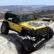
Sab-a-dab-a-doo! The back-country LJ build has officially started

Yes, they did the bending. It was a seamless process using Fusion's sheet metal tools and setting up the sheet metal rules to match SendCutSend's values (mainly the k factor and effective bend radius, which, incidentally, is different for each gauge, but easily found on their website.)

I mentioned in my last post about how much time I spent on the tolerances for the tabs and slots I put on the parts to make assembly easier. I worked through all the SendCutSend production tolerance bands stacking up (including their angular bending tolerance) to come up with the slot size to work for all production variations. As it turns out, their actual accuracy was so good that the slot could have been tightened up considerably. That speaks well for their quality control (or my luck, which is usually not so good :sneaky:)

Thanks! Fusion is a great tool for the community! Been using it mostly for 3D printing but also for my couple purchases on Send-Cut-Send.

Glad they've made it that easy we can see here.
 
  • Like
Reactions: sab
Thanks! Fusion is a great tool for the community! Been using it mostly for 3D printing but also for my couple purchases on Send-Cut-Send.

Glad they've made it that easy we can see here.
The learning curve for sheet metal workflow in Fusion is a bit steep, so if you haven't done sheet metal design before, YouTube is your friend! I wish YouTube (or just the Internet, for that matter) existed when I started my engineering career...
 
The learning curve for sheet metal workflow in Fusion is a bit steep, so if you haven't done sheet metal design before, YouTube is your friend! I wish YouTube (or just the Internet, for that matter) existed when I started my engineering career...

Thanks. Good advice. I learned CAD on Inventory in HS. SolidWorks was the industry standard where I worked after college and I hated it vs Inventor.

Glad AutoDesk created Fusion because it takes a lot of the features from Inventor. Still hadn't used the sheet metal feature. So would definitely use YouTubeUniversity to learn.
 
  • Like
Reactions: Tob
Today's Progress Report:

The laser-cut transmission mount pieces needed deburring prior to welding them. I do a lot of manual deburring with files, so I started there with the main plate that has the bends in it. For the flat side plates, I used a Swag Off-road Chamfer Table:
IMG_7034.webp


I have tiny radiusing bits in the pneumatic chamfering tool, and I really like how easy this makes deburring flat items! After deburring, I ran the random orbital sander with 40 grit over all the pieces and fixtured them up for welding:
IMG_7035.webp


Finished weldment:
IMG_7038.webp


I then mounted it to the transmission, installed the rubber mount, and installed the "cross-member" (I use quotes because it's only the start of a cross-member.) I just wanted to get weight on the mount and see how it did (and it did great.) Speaking of weight, while I had everything in place, and because I'm a curious feller, I put a scale under the cross-member to see just how much weight that mount holds up for this configuration (NSG-370 and Altas 4 Speed T-case):
IMG_7036.webp


Late this afternoon, I went to pick up the skid, so I mounted it, just 'cuz:
IMG_7037.webp


The plan for tomorrow is to continue working on the cross-member. Stay tuned!
 
Today's Progress Report:

The laser-cut transmission mount pieces needed deburring prior to welding them. I do a lot of manual deburring with files, so I started there with the main plate that has the bends in it. For the flat side plates, I used a Swag Off-road Chamfer Table:
View attachment 567818

I have tiny radiusing bits in the pneumatic chamfering tool, and I really like how easy this makes deburring flat items! After deburring, I ran the random orbital sander with 40 grit over all the pieces and fixtured them up for welding:
View attachment 567819

Finished weldment:
View attachment 567820

I then mounted it to the transmission, installed the rubber mount, and installed the "cross-member" (I use quotes because it's only the start of a cross-member.) I just wanted to get weight on the mount and see how it did (and it did great.) Speaking of weight, while I had everything in place, and because I'm a curious feller, I put a scale under the cross-member to see just how much weight that mount holds up for this configuration (NSG-370 and Altas 4 Speed T-case):
View attachment 567821

Late this afternoon, I went to pick up the skid, so I mounted it, just 'cuz:
View attachment 567822

The plan for tomorrow is to continue working on the cross-member. Stay tuned!

We get it - you have all the fab skills and the tools/toys to do it right. What - you couldn't fit a few more clamps on that part to fit it up?

:p J/K. Love watching your work. The above is all envy of your skills.

Can't wait to see the Jeep back on the road. You're a gifted fabricator and we need folks like you sharing with us amateurs here to educate us and build our confidence.
 
What - you couldn't fit a few more clamps on that part to fit it up?
Over the years, I've learned that it's rarely possible to have too many clamps on a weldment, but it's often possible to have two few! I hate warping. ;)

Love watching your work...You're a gifted fabricator and we need folks like you sharing with us amateurs here to educate us and build our confidence.
Thanks, I appreciate the kind words! I created this thread as a two-way conduit - to share my ideas and to learn from others. This forum has many great fabricators on it, and I really enjoy being here!
 
  • USA Proud
Reactions: FarFire70
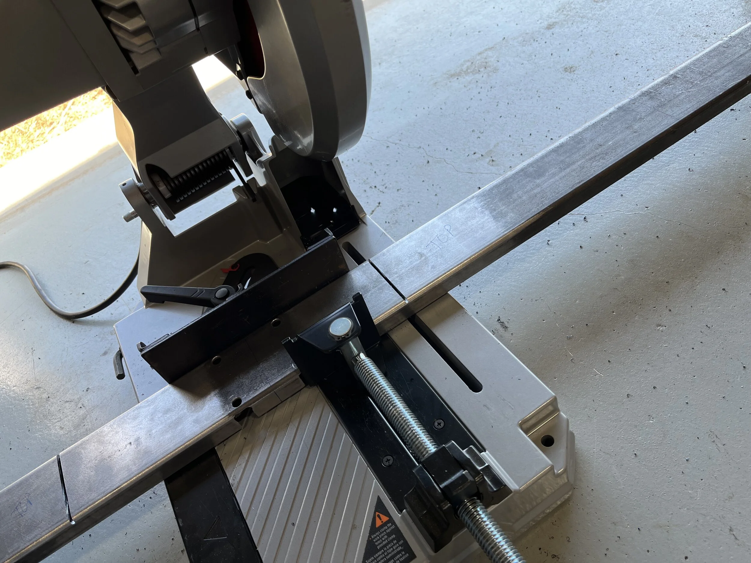
Another day in the shop, and more progress to report! If you've been following along, you'll recall that I designed the center section of the cross-member and started fabricating it, on Wednesday. Today, I continued that. I decided to create the drop angles by wedge-cutting and welding the tubing. I started by laying out my top cuts (using a bend allowance, which worked out to only about 20 thou - yes, I lay things out that precisely!), and then my side wedge cuts. The bottom doesn't get cut - it's bent. The bend is only about 7°, so the wedge cuts are tiny (more on that later). I did the top cuts very carefully on the dry-cutoff saw:
IMG_7041.JPG


In order to limit those top cuts to only the top section of the tubing, I had to start the cut, flip the tubing 180°, and finish it for each of the two cuts. Next, I had to put my thinkin' cap on. The side wedge cuts are so fine that they require a minimal kerf, and the tool I own with the smallest kerf is my pneumatic body saw. The .120" wall thickness is quite easily cut using a quality blade on the body saw, so that's what I used, with great success, if I don't say so myself :rolleyes::
IMG_7042.JPG


The end result:
IMG_7043.JPG


Nearly perfect - woo hoo! Next up was the onerous task of cutting the center section, between the two wedge cuts, straight down the middle on each side in order to weld the round DOM pieces to the bottom section of the tubing. By the way, I wanted the cut down the center because that's what is called the neutral axis, in the engineering world. The neutral axis is where the bending stress is zero, so putting the weld there means imperfections in the weld won't really matter much. I used the side of the fab table to fixture it:
IMG_7044.JPG


The 1-2-3 block shown above was used (one at each end) to set the side of the tubing co-planar with the top of the fab table so that a guide could be used with a jigsaw to get the cut as straight as possible:
IMG_7045.JPG


I didn't cut through completely because I wanted to tack the DOM tubing sections in place so that they'd line up during re-assembly of the two halves:
IMG_7046.JPG


Next, I carefully (it took nearly an hour to get it right) fit the DOM sections into the center section. I mounted the rubber mount and then put a 13mm socket on each nut to ensure the DOM sections were centered on the rubber mount's studs. Some work with a die grinder was necessary to get the fit right. Once I got the DOM sections centered, I tacked them, and used the side of the fab table once again (the guide was left in place) to finish the cuts with the jigsaw:
IMG_7047.JPG


Then I fixtured the bottom center section to weld the DOM to the bottom section of the tubing:
IMG_7048.JPG


After welding those DOM sections in place, I re-assembled the cross-member center section pieces and fixtured them for welding. @FarFire70, this picture's for you:
IMG_7049.JPG


To attempt to keep the 1" height of the cross-member accurate, I used jigsaw blades as shims, since they are close to the cut width. Redneck, huh? As my mama used to say, "son, sometimes you just hafta work with whatya got." I then welded up the center section completely, but be fore-warned - I am incapable of stacking dimes 🤷‍♂️:
IMG_7050.JPG


Fortunately, thanks to @mrblaine's recommendation on the Cubitron fiber discs, by the time I clean this cross member up tomorrow, you'll never be able to tell that I'm a hack welder!

I'll clean everything up tomorrow, and then I'll use the mounted skid to set the angles precisely prior to welding, and if time allows, I'll put the ends on the cross-member for mounting. Stay tuned...

To see the continuation of my work on the cross-member, skip ahead to Post #339.

 
Last edited:
Looking great! Seriously impressive work and attention to detail. Love seeing a design move from CAD to the real world.

Still - see a few spot you could have wedged in a few more clamps. Remember - it's more important to have the part secured, even if that leaves zero room to get any weld laid down. Secured parts first and foremost! ✊
 
  • Haha
Reactions: Tob and sab
Looking great! Seriously impressive work and attention to detail. Love seeing a design move from CAD to the real world.

Still - see a few spot you could have wedged in a few more clamps. Remember - it's more important to have the part secured, even if that leaves zero room to get any weld laid down. Secured parts first and foremost! ✊

Thanks! In this case, the clamps were incredibly necessary. If you've never cut induction-welded tubing before, you've missed the a-ha moment when you get to see exactly how much residual stress is imparted into the tubing during the forming/welding process. There was quite a curve to that bottom half piece once it was "liberated"...
 
After working on the rear frame raise project, I decided to get the Savvy gas tank skid ready for the gas tank and install the tank in it. I started by cutting a radius on the steel pieces with a radius-cutting burr:
View attachment 534936

The burr does a good job of roughing-out the radius, but final sanding with a mini belt sanding makes it smooth:
View attachment 534937

With the steel pieces done, I moved on to the aluminum skid edges with the burr:
View attachment 534938

The cutter is made for steel, so to use it on aluminum, I had to stop frequently to cool it down, and use cutting wax. I finished up with the mini belt sander:
View attachment 534939

With the radiusing complete, I was confident the plastic tank won't be gouged during installation or use, so I fastened the steel pieces to the aluminum skid:
View attachment 534940

I think I got those pieces in the correct holes. Since I have a 1.25" body lift and I'm raising the rear frame, I have the front piece in the top holes and the rear piece in the bottom holes. If I screwed this up, somebody please tell me!

Finally, I installed the straps, inserted the tank, and tightened up the strap bolts:
View attachment 534941

Now, I just need to finish the rear frame raise to install this!

To see the skid after powder-coating, see Post #284.

Got a link to that burring tool?

I want a air bandsaw so this is as good an excuse to pull the trigger for one.
 
Awesome work as usual!

Separate question, how do you like that M12 light?
Thanks! It's a very handy light. The magnet is very strong (almost too much - it's hard to remove from the fab table), and the three axes of rotation make it very easy to position where you need it. I have four very bright ceiling LEDs in the shop, but when welding, shadows get cast that require supplemental light.
 
The magnet is very strong (almost too much - it's hard to remove from the fab table),
We wind up using the longer arm and pulling against it to pop the magnet loose. But, if it was any less strong, it wouldn't work very well on thin sheet metal and that is where it really shines.
 
  • Like
Reactions: sab
But, if it was any less strong, it wouldn't work very well on thin sheet metal and that is where it really shines.
Very true. However, a word of caution is in order regarding using it against painted bodywork - don't! Another issue with the strength of the magnet is that it is impossible to clear of metal shavings that with destroy paint. Compressed air, my usual "clear-a-magnet" tool, doesn't work, so I live with the dirty magnets.
 
  • Like
Reactions: FarFire70
Very true. However, a word of caution is in order regarding using it against painted bodywork - don't! Another issue with the strength of the magnet is that it is impossible to clear of metal shavings that with destroy paint. Compressed air, my usual "clear-a-magnet" tool, doesn't work, so I live with the dirty magnets.

Too bad they don’t make a version with an on-off magnet (perhaps they do?). That’s a game changer when working in metal.
 
Too bad they don’t make a version with an on-off magnet (perhaps they do?). That’s a game changer when working in metal.
Yes, like a mag base for a dial indicator! I think the issue there is weight. They seem to be a lot heavier for the same magnetism level (Tesla?)
 
Mid-day Progress Report:

As I said in my post last night, I can cover up my hack welding skills by being a great grinder:
IMG_7051.webp


Before welding the angled arms, I went to the 30T press to straighten the weld warping:
IMG_7053.webp


Then a bit of fixturing prior to welding:
IMG_7055.webp


And more great grinding after welding:
IMG_7056.webp


If you can't weld like a pro, grind like a pro! 🤫

Next up this afternoon - cut DOM tubing for the mounts at each end, cut holes for them in the rectangular tubing, weld them, and cut the ends off. If time allows, I'll work on mounting brackets for the frame after that.
 
This afternoon, I cut the DOM tubing for the end pieces, cut the holes for them in the ends, and cut each end to length, and I only have a picture of the end result:
IMG_7058.webp


And with the tube in place:
IMG_7059.webp


Next, I fixtured it up for welding. I thought I took a picture of the fixturing, but I did not, so I'll try to describe how I did it. I wanted the tubes parallel to each other and perpendicular to the cross-member. Since the tubes had nicely squared ends, I took two pieces of flat stock, stacked them on top each other, and drilled two 3/8" diameter holes (the mounting bolt diameter) 32.06" on center, which is the desired spacing between the frame rails. That kept them parallel to each other. To get them perpendicular to the cross-member, I placed some .25" spacers between the flat stock and the side of the cross-member. Then, I tacked the tubes in place, removed the fixturing, and finished the welds:
IMG_7060.webp


And here it is mounted above the skid:
IMG_7062.webp


Tomorrow, I'll figure out the mounting tabs to be welded to the frame rails. Stay tuned!