$50 REWARD for the right answer (combo flasher)

Mike Patterson

Member
Original poster
Joined
Jan 29, 2018
Messages
41
Location
Algonquin, IL, United States
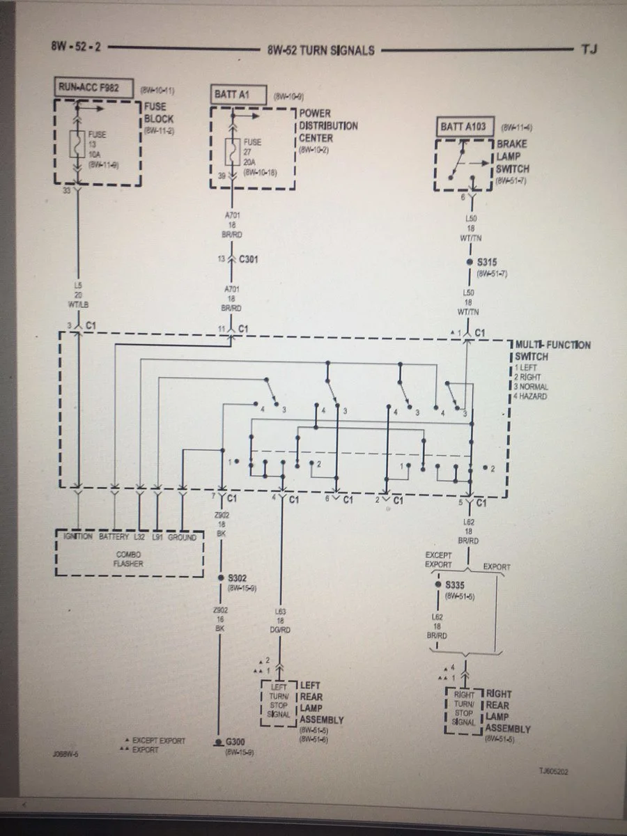
Does anyone know why the Combo Flasher would not flash? I've tried 6 different Combo Flashers(Stock and LED Style) and 3 different Multi-Function Switch's. I can manually make the turn signal bulbs turn on by applying power to either the L32 pin on the combo flasher or connector C1 pin's 2 or 6 as well. With the Combo Flasher removed, I can jump across the battery or ignition to L32 pin and get the selected Turn Signal to light.

Ignition C1, Pin 3 has Power with the key ON. Battery C1, Pin 11 has Power all of the time and Ground C1, Pin 7 has Ground.

It seems all of the wiring works per the diagram. Again, it doesn't matter whether I use LED's or Regular Bulbs. No buzzing and no clicking from the Combo Flasher.

The Headlights, Driving Lights. Brake LIghts all work as they should as well.

Again, if someone out there comes up with the "Fix", I will send you either through Paypal or Chasepay $50 for your time and trouble. Thank you in Advance.

IMG_7151.webp
 
Have you tried it with all OE incandescent bulbs? No LEDs at all. LEDs are not only light bulbs they are diodes which can totally screw up some lighting circuits. Especially a Jeep's flasher circuitry.
 
  • Like
Reactions: Fonz54
I'd check your ground to chassis again. Physically check for a good ground at connection to chassis.
Are you talking about in the Engine Compartment? I have checked, Cleaned or replaced the Hood to Firewall, Firewall to Block and Neg. Battery to Block.

Under the Dash, I've check the G300 Ground as well.
 
Last edited:
If you don't have one already and like to buy tools, I would recommend you look into a power probe II. It is a very good electrical troubleshooting tool, it lets you apply power or ground to a circuit. I think in the end you are going to find a ground issue like Chapman4266 mentioned or a weak connection somewhere. Sometimes it looks like a circuit has power or ground but when you put a load to it, it won't carry enough amps to work. A Power Probe helps you find those kind of problems.
What good is a project or problem if you can't get a new tool out of it?
Best of luck.

B
 
If you don't have one already and like to buy tools, I would recommend you look into a power probe II. It is a very good electrical troubleshooting tool, it lets you apply power or ground to a circuit. I think in the end you are going to find a ground issue like Chapman4266 mentioned or a weak connection somewhere. Sometimes it looks like a circuit has power or ground but when you put a load to it, it won't carry enough amps to work. A Power Probe helps you find those kind of problems.
What good is a project or problem if you can't get a new tool out of it?
Best of luck.

B
Is there another Ground other than what I've listed above that I should check?
 
With the flasher in place, if you flick the turn signal stalk to "left" or "right" turn, what happens? Do the signals light and stay on or just never even turn on?
 
Is there another Ground other than what I've listed above that I should check?

That looks to be the only ground, although there are two places in that ground circuit you should check, S302 and G300.

I googled how much resistance should a good automotive ground circuit have? and found this on a audio forum. It contains some good general information on checking grounds.

B


This is an old GM Technical Service Bulletin,


METHOD OF VERIFYING ' GOOD ELECTRICAL SYSTEM GROUND ' #87-8-139 - (04/07/1987)

VEHICLES AFFECTED: ALL MODELS


When diagnosing electronic systems for incorrect operation, it is often necessary to verify that ground circuits are good. This article is intended to clarify what is meant by the term "good ground" and the preferred tools and methods for verifying it.


A "good ground" is a ground circuit that has a resistance of zero OHMS.


Ground circuit resistance can be measured in OHMS using a digital volt OHM meter (DVOM). When using a DVOM, it must be set on the 200 OHM scale to obtain an accurate measure of the circuit resistance. Many meters have both a 200 OHM scale and a 200 K scale. The 200 K scale will not measure zero OHMS accurately. If you are not sure how the meter is to be set for the 200 OHM scale, refer to the meter operating instructions for proper settings. If the meter is an autoranging or self-scaling meter, read the meter carefully to be sure which scale it is setting itself to.


Before measuring resistance in any circuit, the resistance of the meter should be measured by touching the leads together. A meter with a good battery and leads in good condition will read less than .2 OHMS usually zero. If the leads measure anything more, an accurate measure of the circuit resistance may not be possible.


Always remember - resistance cannot be measured accurately on a "live" circuit, All current flow through a circuit must be stopped by disconnecting its power source before measuring resistance.


Ground circuit resistance can also be checked by measuring the voltage drop across the circuit with a DVOM set on, the 2 volt scale. The voltage drop will be zero across a "good ground" circuit.


Remember, fully understand a meter's functions before using it!


To add to this, a good ground for car audio applications will have a return resistance reading of 1/2 ohm or less. I have yet to have a return reading of 0 ohms. If a ground return reading cannot be made to get below 1/2 ohm by means of the "BIG 3", then it is adviseable to ground direct to the battery. Electricity is an algebra equation, what you do to one side you must do to the other. Pay as much attention to the ground wire as you do the power wire.

The BIG 3 is a great place to start for a good ground, however it is the assumed proper method of grounding. What we are talking about here is the older and wiser 4th brother to the BIG 3 (the BIG 4).

So a proper ground wire will be as follows.

- clean of residue and paint.

- secure.

- have a resistance return of 1/2 ohm or less.

- be of adequate guage to carry the return as compared to the power wire.

To simplify the measuring of the return, use your meter as described. Disconnect the - battery terminal and disconnect the ground wire from you amp. If your dmm probes are not long enough, you will need to create a jumper extension out of some primary wire or whatever wire you have handy. Measure this wire for any resistance reading and subtract it from the total.

Many installers are not aware of this nor practice this method. It takes time and time = $ so don't get all pissy if you had a professional install done and this was not checked. A poor ground connection or high resistance reading may seem trivial under no load, but once you are pounding your nice new amp and it is drawing large amounts of current, this little reading has become a monster reading that has caused many an amp to fail for no apparent reason. It may be noticeable as a extremely hot running amplifier in a short time period, poor output levels or diminishing levels and of course a blown power supply or output section in the amplifier.

While the original article was written for the years gone by, it still is applicable to the newer generation of vehicles. A good ground is not about the amount or size of the metal in the return to the battery but about the resistance through it. Todays vehicles are a combination of metals, spot welds, glued together unibody panels and isolated chassis components. The return through these components is where the resistance reading comes into question and this is what we need people to understand, why the BIG 4 needs to be done if the BIG 3 does not solve the problem.


B

 
Is the Multi-Function Switch being properly installed, with all connections making proper contact? If the relay is buzzing, something is not making a solid contact, could be some interference, or all of the relays you are using are fried. Do you have any aftermarket lights or audio where their power and ground wires may be wrapped around the main wire harnesses? Did you piggyback off any grounds using aftermarket equipment?
 
Are you using a meter to test these grounds? What are your resistance readings? Have you tried a voltage drop test across different parts of the circuit to see if corrosion or a bad splice is eating up voltage?

Another suggestion, instead of paying $50 to whoever gives you the right answer why don't you become a supporting member of the forum and kick @Chris a few bucks to keep this place going? People here are going to help regardless of whether you offer money or not.
 
Last edited:
Are you talking about in the Engine Compartment? I have checked, Cleaned or replaced the Hood to Firewall, Firewall to Block and Neg. Battery to Block.

Under the Dash, I've check the G300 Ground as well.
Yes I am. What you're describing most likely is a ground issue. Shiny metal on all of them and soldered connections to eliminate any doubt. It may be something else, but ensuring good ground allows you to move forward.
 
Is the Multi-Function Switch being properly installed, with all connections making proper contact? If the relay is buzzing, something is not making a solid contact, could be some interference, or all of the relays you are using are fried. Do you have any aftermarket lights or audio where their power and ground wires may be wrapped around the main wire harnesses? Did you piggyback off any grounds using aftermarket equipment?
The MFS is properly installed. I have tried 3 different Unit's. They buzz intermittently. The only lights that are now no longer stock are the headlights. I do have an aftermarket Radio and speakers. No piggybacking of Grounds. Thoughts?
 
The MFS is properly installed. I have tried 3 different Unit's. They buzz intermittently. The only lights that are now no longer stock are the headlights. I do have an aftermarket Radio and speakers. No piggybacking of Grounds. Thoughts?

Do you have an amplifier, or amplifiers, in addition to the head unit? What about speakers, did you run new speaker wire?

I am asking these questions to see if your aftermarket audio system could be interfering. Do you ever any whine or hiss from the speakers, like "alternator whine"?

What headlights are you using? Did they have an aftermarket harness. Is one needed for the headlights you have?

Any chance you crimped a wire, possibly a ground wire was tangled, or wiggled and you tugged hard enough that the copper wire is no longer contacting the terminal connector, or contacting enough of the terminal, this could be in an OEM or aftermarket harness, or stand-alone terminal connector.
 
Do you have an amplifier, or amplifiers, in addition to the head unit? What about speakers, did you run new speaker wire?

I am asking these questions to see if your aftermarket audio system could be interfering. Do you ever any whine or hiss from the speakers, like "alternator whine"?

What headlights are you using? Did they have an aftermarket harness. Is one needed for the headlights you have?

Any chance you crimped a wire, possibly a ground wire was tangled, or wiggled and you tugged hard enough that the copper wire is no longer contacting the terminal connector, or contacting enough of the terminal, this could be in an OEM or aftermarket harness, or stand-alone terminal connector.
Thank you for the input but A buddy of mine came over with a Brilliant Idea! I still don't understand how or why it worked but it did. After trying 7 different OE Style Flasher Relay's, he plugged in an old school VW Bug Style flasher with a couple of jumpers and "Pow", they worked. I've re-done 50-60 TJ's and have never run into anything like this. Crazy.

All, thank you for your idea's!

IMG_7157.webp
 
Thank you for the input but A buddy of mine came over with a Brilliant Idea! I still don't understand how or why it worked but it did. After trying 7 different OE Style Flasher Relay's, he plugged in an old school VW Bug Style flasher with a couple of jumpers and "Pow", they worked. I've re-done 50-60 TJ's and have never run into anything like this. Crazy.

All, thank you for your idea's!

View attachment 133634

That is wild, so the OEM-like relay was the issue the entire time.