Higher horses, higher revs & even higher torque, a streetable LJ engine swap

How did you determine the sizes/thickness of the plate used for the mounts and gussets? Looks kind of small to the untrained/unfamiliar eye... Wondering if there’s a method to it all or just eyeballing it.

Any idea if the frame needs to be beefed up for the weight of then engine. Read that Jeep did something of the likes when they swapped in the bigger and heavier V8 in their Wrangler 392.

I had it in my mind to make them from 1/8" so as to prove a point that big thick mounts aren't necessary. I added the gussets to further strengthen them and then sent the design over to a much more experienced friend who agreed that the design should hold up well with 1/8". 9/16" bolt will also be torqued to around 110ftlbs which gives considerable strength to the bracket by adding a "top" to it.

The LS engine is much lighter than the weight of the inline 6 so no concerns as far as weight go. However I have had concerns about the torque of the engine wanting to rip apart the Jeep. I'll be using a big thick belly skid which will add torsional strength to the frame and I also have the hoop spreader that goes over top of the engine. Looking at other swaps this seems to hold up well.
 
TBH i'm not sure i'd want 1/8" material there. like you mention weight is not the big issue, but the torque is.
kinda why i mentioned i had tabs. and any torsional shift/slip will wallow out that hole real dam quick.
but i'm no engineer and hopefully your correct.
 
TBH i'm not sure i'd want 1/8" material there. like you mention weight is not the big issue, but the torque is.
kinda why i mentioned i had tabs. and any torsional shift/slip will wallow out that hole real dam quick.
but i'm no engineer and hopefully your correct.
As long as the bolt is torqued, it shouldn't oval, correct?
 
that's the claim.
but what kind of torque is that power plant gonna push?
maybe it's just me. this is a location that i could not consider for a minimalist build strategy.

the fact that it's small and compact does lend to it's strength, boxed is even better. just took me a bit by surprise seeing 1/8" material, you got a lot of $ hangin of those brackets.

will 110# hold it if you jump on that pedal? or even worse god forbid, what if it flopped you trust them for that too?
 
that's the claim.
but what kind of torque is that power plant gonna push?
maybe it's just me. this is a location that i could not consider for a minimalist build strategy.

the fact that it's small and compact does lend to it's strength, boxed is even better. just took me a bit by surprise seeing 1/8" material, you got a lot of $ hangin of those brackets.

will 110# hold it if you jump on that pedal? or even worse god forbid, what if it flopped you trust them for that too?

The engine has around 430ftlbs of torque at peak.

A thicker material isn't going to change the clamping force that a 9/16" bolt provides. So all that a thicker material will help with is preventing the mount itself from bending.
 
that's the claim.
but what kind of torque is that power plant gonna push?
maybe it's just me. this is a location that i could not consider for a minimalist build strategy.

the fact that it's small and compact does lend to it's strength, boxed is even better. just took me a bit by surprise seeing 1/8" material, you got a lot of $ hangin of those brackets.

will 110# hold it if you jump on that pedal? or even worse god forbid, what if it flopped you trust them for that too?
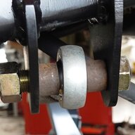
Factory TJ front lower control arm mount is slightly thicker than 1/8". The bolt sleeves in the joint are clamped to the insides of the slotted mount by no more than 40% of the surface area available on the end of the bolt sleeve. How much torque or force is developed when a front tire hits a pothole at freeway speed?

You were in the "trust what you know" thread, forget it already? The 1/8" he is using has much shorter lengths to the welds, it has gussets, it can not possibly go anywhere or fail.

edit- the clamping force generated by a grade 8 9/16" bolt torqued properly exceeds 16,000 lbs. There is no chance the ends of that bolt sleeve will dislocate.
 
Last edited:
ya i remember that thread and this seems it would exceed the load that those frame end trans mounts will see. it's still anchored at the trans mount, the frame ends merely hold all that up.
this MM is a direct anchor point.

ay, if y'all trust it who am i but some fool that had to ask.
 
ya i remember that thread and this seems it would exceed the load that those frame end trans mounts will see. it's still anchored at the trans mount, the frame ends merely hold all that up.
this MM is a direct anchor point.

ay, if y'all trust it who am i but some fool that had to ask.
The cool thing about all of this is that not only do we get to discuss theory, I'm also going to be testing it offroad. So it should quickly become evident if it works or doesn't work.
 
Are the weight differences in your thread somewhere? I have yet to look, just curious.

I don't have official weights or have a way to weigh them myself. However, according to the internet there's about a 75-100lb difference with each fully dressed. I can testify that there's a difference too because I can feel it in the hoist.

I'm sure that I'll be gaining some of that weight back with the Atlas vs NP231. And the transmissions can both be lifted and feel roughly the similar weight.

Once I have the coilovers back in I'll be able to see the difference (and will likely have to swap springs).

Edit: It's probably also important to note that I have an aluminum block LS.
 
Last edited:
  • Like
Reactions: Fouledplugs
I’m with you.
So, if I mock that up with a similar bolt and tab arrangement and put it in my shop press that has a pounds of force gauge on the ram, what number would you like to see before you are satisfied that it won't die a horrible death?

A few things to consider to help you along. The torque is hardest to resist the closer to centerline the mounting points are. The further they are from centerline, the less strong they have to be.

Motor weighs about 450 lbs, you can hold that up with a 1/4" grade 8 bolt so weight isn't a concern. We just have to account for rotational resistance when the motor is under load, one side lifting, other side pushing down.

So, what is the number?
 
Factory TJ front lower control arm mount is slightly thicker than 1/8". The bolt sleeves in the joint are clamped to the insides of the slotted mount by no more than 40% of the surface area available on the end of the bolt sleeve. How much torque or force is developed when a front tire hits a pothole at freeway speed?
sorry, my gut tells me i wouldn't trust it.
last comments and i drop this.............this also sits in a positioning washer that is locked in a horseshoe weldment, and IDK if a pothole couldn't move it without those washers. but if y'all say it's impossible, i have no proof to challenge you.

then there is the matter of tempering the thin metal during the weld process.............and all those pics everybody posts of cracks along the welds.
 
Last edited:
sorry, my gut tells me i wouldn't trust it.
last comments and i drop this.............this also sits in a positioning washer that is locked in a horseshoe weldment, and IDK if a pothole couldn't move it without those washers. but if y'all say it's impossible, i have no proof to challenge you.

then there is the matter of tempering the thin metal during the weld process.............and all those pics everybody posts of cracks along the welds.
The fact that you bring in the horseshoe means you don't really understand what is going on. The horseshoe is only there to move the bolt back and forth in the slot with eccentric washers until the bolt is tightened down. Once the bolt is tight, they have no further function and are not in play at all. In fact if they were and the eccentric washer were to contact the inner face, all it would do is keep moving and rotate to allow the bolt to slide in the slot. That doesn't happen because they are not locating the washer under load, the bolt is.

So, per above, give me a number and maybe post up a picture of a lower control arm mount that has cracked at the welds from an impact load at speed hitting a pothole.
 
you ask for the impossible. there is no way to gauge what a stress fracture could have occurred from. be it an instant event or a long term leverage issue. but along a weld it's usually the temper that has made that line more brittle.
lets leave this at............1 might suggest not nukin that material when welding.

and the other question is also impossible to pinpoint without a complicated equation of mass and speed compounded by available torque and leverage.
 
you ask for the impossible. there is no way to gauge what a stress fracture could have occurred from. be it an instant event or a long term leverage issue. but along a weld it's usually the temper that has made that line more brittle.
lets leave this at............1 might suggest not nukin that material when welding.

and the other question is also impossible to pinpoint without a complicated equation of mass and speed compounded by available torque and leverage.
Stress fractures generally occur when there is movement to allow the material to flex. With the gussets on the two end bolt tabs, that movement is negated. With the movement stopped, the likelihood of a stress fracture due to front and back forces working on the tabs to crack them is very minimal.

That only leaves the motor trying to tear the tabs off of the mounting plate and trying to rip the bolt through the material. How much force would it take to rip the bolt through the material?

BTW- if I am asking for the impossible, how can you tell it is or isn't enough strength?