Solid round bar versus round tube

I just did my own CA last year and I never ran a single number (other than length). I just looked at what others have done and what seemed to have worked for the long run and then also looked at availability. Availability and price is a driving factor! Doesn't make a lot of sense for us to design a one off diameter control arm out of an exotic material is er can't afford to have them made or can't readily be made when WOD (or similar) has a dia and material that has been proven to work on similar rigs at similar lengths.

I use it to compare or did use it to see if I wanted 4130 tube or solid aluminum. When I figured out that I couldn't decrease the diameter of the steel arm and do the fab here, I waited on the solid aluminum. If it wasn't for folks putting up calculators like that, I'd just be guessing and depending on them that really are not doing anything more accurate.
 
  • Like
Reactions: gasiorv
I remember from physics that an "impulse" force has a greater effect than a "constant" force. I think y'all have been talking about a constant force (or stress). How about one of the MEs chiming in regarding impulse force, i.e. what you get when your Jeep falls onto a rock?

A shaft designed to take 1000hp from a diesel is going to be larger than one from a 1000hp turbine engine
 
A shaft designed to take 1000hp from a diesel is going to be larger than one from a 1000hp turbine engine

Power doesn’t matter. Driveshafts are designed based on peak torque, and torque can be calculated from horsepower and rpm. Turbine engines spin much faster than piston engines, so when power output is the same, a diesel engine makes a lot more torque. For example, a 1,000 hp diesel engine that makes peak torque at 3,000 rpm makes a peak torque of about 1,750 ft-lb, while a 1,000 hp turbine engine that makes peak torque at 15,000 rpm makes a peak torque of about 350 ft-lb.

So, the turbine engine will have a significantly smaller and lighter driveshaft, but not because it’s a smoother torque delivery…
 
Oh man...This post gave me flashbacks to college...I headed straight into manufacturing engineering since I don't have a "head" for math. I'm always impressed when someone can whip out the calculations as @sab did, even if he did make a mistake. I would have spent all day looking that stuff up in my old textbooks and trying to remember how to solve the problems.

Don’t be too impressed. I’ve worked in design engineering my whole career, and even though I practice civil engineering now, I did so many calculations like the one above over the decades I practiced mechanical engineering that it’s etched in my brain. I’m sure you have manufacturing engineering principles etched in your mind, too. I had a few mandatory manufacturing engineering classes in college, and it would take me all day to make sense of those, too!

It’s disappointing that age has eroded those equations that once came immediately to mind. 😞 Like gasiorv, I should have realized that moment of inertia has units of in^4.


 
Power doesn’t matter. Driveshafts are designed based on peak torque, and torque can be calculated from horsepower and rpm. Turbine engines spin much faster than piston engines, so when power output is the same, a diesel engine makes a lot more torque. For example, a 1,000 hp diesel engine that makes peak torque at 3,000 rpm makes a peak torque of about 1,750 ft-lb, while a 1,000 hp turbine engine that makes peak torque at 15,000 rpm makes a peak torque of about 350 ft-lb.

So, the turbine engine will have a significantly smaller and lighter driveshaft, but not because it’s a smoother torque delivery…

You're right, i should have said torque. That is what i was thinking of
 
  • Like
Reactions: sab
1702695578011.gif
 
Do the same principles apply to square/rectangular solid material vs. tube?

I'm trying to think in terms of a Jeep specific application such as a rub rail on a rock slider. Which is stronger? I ask as I am in the middle of a rock slider project and just have a bit of curiosity as to the why and how.

I really like when Blaine posts these kind of topics.
 
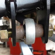
That is also one of the reasons why joints fail in high strength shafts and stock shafts fail at the yokes with far fewer broken joints. The yoke strength affects the tip over and brings in a much higher level of fixity in the high strength versions. Thusly, with both pins looking the same.
View attachment 482623

I've had some of those 😃

5-806, Yukon chromo inner, Spicer 35 spline outer machined for full snap rings.

Have pics somewhere of the ears pulled out of Warn chromos with the 760 trunions intact. But most look just like that.

memorialday2012022.webp


IMAG0330.webp


IMAG0380.webp
 
I remember from physics that an "impulse" force has a greater effect than a "constant" force. I think y'all have been talking about a constant force (or stress). How about one of the MEs chiming in regarding impulse force, i.e. what you get when your Jeep falls onto a rock?

It's really hard, if not impossible to determine analytically in anything beyond the most simplified theoretical scenarios...at best it ends up being a mathematical model developed using data from past laboratory testing and then confirmed with more lab testing. Or in aftermarket you mostly skip the modeling and just go with what has been known to work.
 
Or in aftermarket you mostly skip the modeling and just go with what has been known to work.
I'm installing some GR mini boatsides. I'll get a pic of the welds that hold the small step on. They are larger than any weld you would use on any part of the rig except where they insert large diameter tubes into a steering knuckle. Yeah, that much weld has been known to work but do we really need something almost a 1/2" across the face to hold 3/16" material to 3/16" material?
 
Do the same principles apply to square/rectangular solid material vs. tube?

I'm trying to think in terms of a Jeep specific application such as a rub rail on a rock slider. Which is stronger? I ask as I am in the middle of a rock slider project and just have a bit of curiosity as to the why and how.

I really like when Blaine posts these kind of topics.
In general, if it is a beam in bending the outer fibers take the axial loads and the web (vertical flange of square tube) take the shear. So the same would apply for a bending load. However, a rub rail would not typically be subject to pure bending but would actually be a point load trying to "crush" or compress the rail (between the rock and the slider or tub). A tube with same outer dimensions as a solid bar would be weaker on this loading scenario but it still may be strong enough, depends on the actual impact and footprint of where the impact is made.
 
I'm installing some GR mini boatsides. I'll get a pic of the welds that hold the small step on. They are larger than any weld you would use on any part of the rig except where they insert large diameter tubes into a steering knuckle. Yeah, that much weld has been known to work but do we really need something almost a 1/2" across the face to hold 3/16" material to 3/16" material?

I am assuming purely for looks and not function. I have those sliders and more than one person has commented on how they like those welds.
 
I'm installing some GR mini boatsides. I'll get a pic of the welds that hold the small step on. They are larger than any weld you would use on any part of the rig except where they insert large diameter tubes into a steering knuckle. Yeah, that much weld has been known to work but do we really need something almost a 1/2" across the face to hold 3/16" material to 3/16" material?

A close friend of mine could answer that question (given the right inputs such as the predicted load) but I can say with some certainty that his answer would be smaller what you're describing. Though I doubt GR could put a number to what load they're designing for because of how difficult it is to quantify dynamic loads.

A funny story, when he interviewed with the company we worked for they gave him a problem to solve - to calculate the required size of a fillet weld for a given load, etc. He ran the numbers and he knew it was wrong, so he told them he knew it couldn't be right and must have made an arithmetic error, but his answer was close to an inch and at least double the thickness of the plates being joined. They saw his error and decided it was forgiveable and hired him anyway, but on his first day he came to his desk to find a welcome gift of his calculated weld about 6" long. The damn thing weighs several pounds and took like 20 passes on two pieces of about 1/2" plate and he's had it on his desk for 17 years.
 
A close friend of mine could answer that question (given the right inputs such as the predicted load) but I can say with some certainty that his answer would be smaller what you're describing. Though I doubt GR could put a number to what load they're designing for because of how difficult it is to quantify dynamic loads.

A funny story, when he interviewed with the company we worked for they gave him a problem to solve - to calculate the required size of a fillet weld for a given load, etc. He ran the numbers and he knew it was wrong, so he told them he knew it couldn't be right and must have made an arithmetic error, but his answer was close to an inch and at least double the thickness of the plates being joined. They saw his error and decided it was forgiveable and hired him anyway, but on his first day he came to his desk to find a welcome gift of his calculated weld about 6" long. The damn thing weighs several pounds and took like 20 passes on two pieces of about 1/2" plate and he's had it on his desk for 17 years.

Or, we look at the welds that hold the control arm mounts to the frame and figure that anything just a tiny bit better than that is more than plenty.
 
Or, we look at the welds that hold the control arm mounts to the frame and figure that anything just a tiny bit better than that is more than plenty.

Exactly. I'm not a welding engineer and there are several people better at this than me already posting in this thread so I could very easily be wrong, but I would question the need for any weld with a cross section larger than the parts being joined.
 
Caveats- This is just a rough way to figure out the questions to ask about something. Something like a greasable bolt with a small hole drilled in it for a grease path.

I have to take issue with including the greaseable bolt with this discussion.

Tube works so well because the strength of a beam in bending is a function of depth^3, The center contributes almost nothing here, as your example of a 1/8 hole illustrates. There's a huge material efficiency benefits to be gained by increasing diameter.

Bolts are typically designed to work by providing clamping force, so they are loaded in tension. This is a function of the area of the cross-section, and any area taken out of the center weakens the bolt just as much as area taken off the outside (smaller d). This calculator does not apply to tension calculations.

Obviously greaseable bolts work in many situations as the tiny hole doesn't remove enough of the cross section to matter. I just don't want people to conflate the concepts. This is the reason we see tubing everywhere (huge benefit to primary task) but very few hollow bolts (0 benefit to primary task).
 
Actually, the tensile load from bolt stretch is typically very small compared to the tensile strength of the bolt. In contrast, the shear stress on a bolted joint used in a single- or double-shear joint (like a control arm mount) is usually the design constraint. In practice, we rarely even considered bolt stretch in our designs. Rod bolts and head bolts being one exception, but that's because they aren't shear joints. They are loaded in tension. But, both axial tensile stress and shear stress are based on area, so removing the center is not trivial. For example, putting a 1/8" hole in a 1/2" diameter bolt reduces both the axial tensile strength and the shear strength by about 6%.
 
  • Like
Reactions: freedom_in_4low
I have to take issue with including the greaseable bolt with this discussion.

Tube works so well because the strength of a beam in bending is a function of depth^3, The center contributes almost nothing here, as your example of a 1/8 hole illustrates. There's a huge material efficiency benefits to be gained by increasing diameter.

Bolts are typically designed to work by providing clamping force, so they are loaded in tension. This is a function of the area of the cross-section, and any area taken out of the center weakens the bolt just as much as area taken off the outside (smaller d). This calculator does not apply to tension calculations.

Obviously greaseable bolts work in many situations as the tiny hole doesn't remove enough of the cross section to matter. I just don't want people to conflate the concepts. This is the reason we see tubing everywhere (huge benefit to primary task) but very few hollow bolts (0 benefit to primary task).

I'm acutely aware of how bolts function for the vast majority of our uses. I'd make the case that a fine thread bolt with a small hole for grease path is still stronger than the same grade and diameter in coarse thread. Someone really good with math will have to show me why I'm wrong.
 
I'm acutely aware of how bolts function for the vast majority of our uses. I'd make the case that a fine thread bolt with a small hole for grease path is still stronger than the same grade and diameter in coarse thread. Someone really good with math will have to show me why I'm wrong.

Grease hole or not the fine thread bolt has better tension ability . The base diameter of the bolt is larger with fine thread, and of course there are more thread engagement per inch . But the side-down is you can gall fine threads easier.
 
  • Like
Reactions: DB04RedJeep