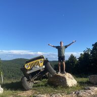
Sab-a-dab-a-doo! The back-country LJ build has officially started

I have no idea, but I keep track of weight changes down to .01 lb. I learned in my racing days that the only way to have a competitively light vehicle is to look at every part. It's easier to take 10% off each part than it is to take 100% off a single part...

I understand why you're trying to find the exact weights. I was more curious about what the difference might be between them.
I've always had 97-02 rigs so haven't ever worked on a newer one.
 
  • Like
Reactions: sab
That is surprising. Isn't the later skid larger?
Yes, but they deleted the weld in crossmember that the manual transmission mount lands on.
1730070276654.webp
 
Woo hoo! For the first time in five weeks, my LJ doesn’t need help holding its tummy in:
IMG_7066.webp


I’m taking Mrs. sab to dinner now, but I’ll post today’s activities later this evening when I get home. It includes a plot twist and a phone call with Mr. Blaine. Here’s a hint for those paying attention:
IMG_7065.webp


Stay tuned!
 
Alright, so here's today's official progress report. Making the mounting brackets for the cross-member was pretty straightforward, so no pictures. I drilled the holes first in one big strip of steel, then cut them off to length and rounded the ends. Then I mounted the cross-member above the skid plate with some .010" shim stock between the cross-member and the skid. I did this to attempt to ensure that 100% of the weight of the transmission mount was on the cross-member once the brackets are welded to the frame. Then, I lined everything up and welded the outsides completely, and heavily tacked the top and bottom on the insides. I let it cool back to ambient temperature, removed the skid and cross-member, and welded the insides. Here's a close-up of one side after reinstalling for a picture:
1730078764808.png


I didn't have the right length bolts, so that's actually a cut piece of the original all-thread that came with the Atlas for the twin stick linkages. Proper Grade 8 bolts will be on their way tomorrow.

And here's the plot twist I teased before dinner. When I was removing the skid, I was getting fine aluminum flakes falling as I loosened the flat-head bolts holding the skid plate on. Thinking that was odd, I investigated. Looking at the countersunk holes, I could see a very sharp witness mark at the top of the taper (the widest part, at the bottom surface of the skid when installed). Right away, I thought, "that meathead machinist put an 82° countersink on this skid!" I was very explicit about it requiring a 90°. However, as it turns out, measuring the included angle of a countersunk hole is not so easy!

To confirm, I painted one of the tapers with blue Dykem and tightened it to see what contact I had in the taper. That's the photo in my teaser post above, and if you look closely, you can see that the only contact, where the Dykem is rubbed away, is a very fine line at the widest part of the head, corresponding to the witness mark I was seeing in the skid's hole:
1730079979734.png


Crap - now what?

Mr. Blaine and I had been conversing via email right before this, so I mentioned my issue in an email. A short time later, he called me, and we discussed possible solutions. He came up with the best one (not surprising at all), as he said, "I just thought of the best solution, but you're not going to like it." I groaned, and he said, "you can drill out the M12-1.75 nutserts and replace them with the earlier 1/2-13 nutserts because the 1/2-13 flatheads have an 82° countersink." He's right, I don't like it - installing those huge nutserts is a special kind of fun. However, he's also right that it's the best solution.

So, now, before I can put this back together, I'll be drilling out 14 metric nutserts and replacing them with SAE. Fun! Stay tuned...

 
Last edited:
  • Like
Reactions: MikeE024
Alright, so here's today's official progress report. Making the mounting brackets for the cross-member was pretty straightforward, so no pictures. I drilled the holes first in one big strip of steel, then cut them off to length and rounded the ends. Then I mounted the cross-member above the skid plate with some .010" shim stock between the cross-member and the skid. I did this to attempt to ensure that 100% of the weight of the transmission mount was on the cross-member once the brackets are welded to the frame. Then, I lined everything up and welded the outsides completely, and heavily tacked the top and bottom on the insides. I let it cool back to ambient temperature, removed the skid and cross-member, and welded the insides. Here's a close-up of one side after reinstalling for a picture:
View attachment 568477

I didn't have the right length bolts, so that's actually a cut piece of the original all-thread that came with the Atlas for the twin stick linkages. Proper Grade 8 bolts will be on their way tomorrow.

And here's the plot twist I teased before dinner. When I was removing the skid, I was getting fine aluminum flakes falling as I loosened the flat-head bolts holding the skid plate on. Thinking that was odd, I investigated. Looking at the countersunk holes, I could see a very sharp witness mark at the top of the taper (the widest part, at the bottom surface of the skid when installed). Right away, I thought, "that meathead machinist put an 82° countersink on this skid!" I was very explicit about it requiring a 90°. However, as it turns out, measure the included angle of a countersunk hole is not so easy!

To confirm, I painted one of the tapers with blue Dykem and tightened it to see what contact I had in the taper. That's the photo in my teaser post above, and if you look closely, you can see that the only contact, where the Dykem is rubbed away, is a very fine line at the widest part of the head, corresponding to the witness mark I was seeing in the skid's hole:
View attachment 568479

Crap - now what?

Mr. Blaine and I had been conversing via email right before this, so I mentioned my issue in an email. A short time later, he called me, and we discussed possible solutions. He came up with the best one (not surprising at all), as he said, "I just thought of the best solution, but you're not going to like it." I groaned, and he said, "you can drill out the M12-1.75 nutserts and replace them with the earlier 1/2-13 nutserts because the 1/2-13 flatheads have an 82° countersink." He's right, I don't like it - installing those huge nutserts is a special kind of fun. However, he's also right that it's the best solution.

So, now, before I can put this back together, I'll be drilling out 14 metric nutserts and replacing them with SAE. Fun! Stay tuned...


I don't like it any more than you do but I can't come up with anything else as efficient that we can get parts to fix in a hurry. That and I was wrong on my countersinks. We fixed some metric 90's with an 82 to get some longer bolts in some studio lighting clamps for a camping rack.
 
  • Like
Reactions: sab
I don't like it any more than you do but I can't come up with anything else as efficient that we can get parts to fix in a hurry. That and I was wrong on my countersinks. We fixed some metric 90's with an 82 to get some longer bolts in some studio lighting clamps for a camping rack.
Thanks again, Mr. Blaine. You are a true gentleman!
 
Not a big progress report this evening and no pictures. I re-installed the Atlas in order to check the final vertical location of the transfer case with the cross-member and skid in place with all the weight on the rubber mount. The transfer case is about 1/4" too low (Mr. Blaine warned me that the mount compressed more than I would expect, and he was right). Fortunately, this result was not unexpected because I purposely erred on the low side, and I had some shims designed, just in case. Those designs went to SendCutSend this evening. I'll be able to dial in the vertical location in .030" increments with them.

I also made a list of all the tub modifications necessary to finish the installation, and it's more extensive than I ever would have imagined:
  1. I have to fix the tub kink I created. I think I'll have to cut the spot welds between the two layers of the tub in order to straighten everything, and then re-weld the layers together. Fun.
  2. I need to cut a clearance hole for the Atlas twin stick shift tower and then make a cover for it.
  3. I need to bump out some clearance for the case side cable shifter mount for the planetary.
  4. I need to mount the planetary shifter, which is going to be a bit tricky because the only place it will mount is behind the transmission shifter and to the right of the parking brake handle, which is in an area of the tub that is two layers. I don't have a solid plan for this, yet.
  5. The hole for the twin stick needs cutting and bending to make clearance for the front shifter in low.
  6. Once #5 is done, I need to make a cover for the twin stick hole because it will be bigger than the rubber boot from Atlas will cover.
I've learned that the Atlas 4 speed installation with an NSG-370 and a 1" drop skid is definitely not for the faint of heart. The floor of the tub needs a lot of work to fit everything between it and the skid.

I ended the day by removing the skid, cross-member, transmission mounting bracket, Atlas, and everything holding the transmission on (it's strapped to the jack right now). Tomorrow, I have other commitments until mid-afternoon, but when I finish that up, I'll pull the transmission to gain full access to the underside of the tub in order to make those mods. I'm also going to paint the cross-member and transmission mounting brackets (I made two, so I have a spare).

Stay tuned!
 
Why did you choose to not bolt the skid plate to the cross member?

P.S. this is a great read - I love all the fabrication and engineering commentary, and can’t wait for the full FEA results!
 
P.S. this is a great read - I love all the fabrication and engineering commentary, and can’t wait for the full FEA results!
Thanks, but don't hold your breath for FEA results... :)

Why did you choose to not bolt the skid plate to the cross member?
I did consider it, and I consulted Mr. Blaine about it, to hear his experiences in rock-crawling situations. The only "pro" I could think of for why to do it would be to increase torsional rigidity when the frame is twisting, like when you're flexing opposite sides front-to-rear. The increase in rigidity is not that great because the cross-member and the skid provide most of the rigidity.

With that small "pro" in mind, I then considered the "cons"), which were more numerous:
  1. More work installing the screws
  2. More weight for the screws, nuts or nutserts, and sleeves (if used)
  3. More work removing the skid for maintenance
  4. Since I wanted the angled sides of the cross-member to lift off the skid (only the center portion of the cross-member touches the skid) in order to keep the mounting tabs from dropping below the bottom of the frame rails, only the center section would have screws, anyway
  5. I assumed that my cross-member design would result in some wonky warping, and as such, it would be difficult to get the skid and the cross-member to seat flat against each other (and that assumption was confirmed - the cross-member is far from flat in the center)
 
Today, I prepped and painted the transmission mounting brackets and cross-member that I made, along with two used OEM transmission mounts:
IMG_7090.JPG


Then, I used a ball-end cylindrical carbide burr to cut about 3/16" of clearance in the top of the skid for the lowest corner (rear, driver-side) of the Atlas oil pan:
IMG_7091.JPG


Finally, I removed the NSG-370:
IMG_7087.JPG


Having that out of the way gives great access to perform all the work I need to do on the tub floor. The numbers in this picture correspond to the numbers of the list in Post #371:
IMG_7089 with Numbers.jpg


Numbers 1, 3, and 4 are complicated because they are located in areas where there are two layers for the tub that are spot-welded together. The two layers are why the tub buckled (#1) when I bumped out clearance using the hydraulic ram. This time, I'm going to cut the spot-welds out so that the two layers can move relative to each other. I've already started on #3, and it's going much better!

Edited to add: With the NSG-370 out, I'm going to take the opportunity to replace input and output seals, countershaft hole plug (below the input seal), pilot and throw-out bearings, clutch fork pivot ball, and maybe the clutch. I say maybe on the clutch because this rig only has 55k miles on it, and the clutch is probably still got a lot of life left in it (didn't really look at it today).

Stay tuned...
 
I made a little more progress today. In the morning, I confirmed with the machinist that the countersinking was done with an 82° cutter (he claims it was marked as a 90°, but I'm not sure I believe him - that's too convenient an excuse.) I then went out to the shop and drilled out half of the metric nutserts, and it went much better than I expected it would. After that, I went down to the metals dealer and bought a sheet of 20g cold-rolled mild steel to use for any panels for the floor that are needed. That pretty much shot the morning.

In the afternoon, I straightened up a bit, and then I drilled out the remaining nutserts:
IMG_7097.webp


As you can see, I was able to fish all the bodies out of the frame rails using the bore camera and two different magnets "on flexible sticks". My OCD wouldn't allow me to leave those rattling around in the frame. :sneaky: I then turned my attention back to the tub mods. Until I looked, I didn't realize how many spot welds between the two layers of the tub there were right in the area where I used the ram. I should have paid much more attention! If I did, I don't believe I'd have kinked the floor because I'd have cut the welds first. If you're reading this because you're getting ready to do a similar tummy tuck/Atlas 4-speed installation, mind those spot welds! There are eleven welds in an area about 5" x 8" that I cut this afternoon (the upper right rectangle below), including two that hold the right front seat bolt boss to the floor for the driver-side seat (removed before the picture:
1730336345161.webp


The lower left rectangle above is where I've been working to bump out some clearance for the case side cable shifter mount for the planetary. If you look closely, you can see how much the top layer has moved, relative to the bottom layer, after hammering about 1/2" of clearance there. In hindsight, I should have used a ball end burr to grind the centers of the remainders of the spot welds prior to hammering because the top layer won't sit flush now. Instead, I'm going to use the burr to slot the holes in the bottom layer to give clearance for those weld centers. I'll then put some temporary self-tapping screws in to pull the two layers back together, then I'll re-weld those spot welds, remove the screws and plug-weld the screw holes. I'll have some painting to do up top, too. Fun!

Stay tuned...
 
  • Like
Reactions: FarFire70
Thanks, but don't hold your breath for FEA results... :)


I did consider it, and I consulted Mr. Blaine about it, to hear his experiences in rock-crawling situations. The only "pro" I could think of for why to do it would be to increase torsional rigidity when the frame is twisting, like when you're flexing opposite sides front-to-rear. The increase in rigidity is not that great because the cross-member and the skid provide most of the rigidity.

With that small "pro" in mind, I then considered the "cons"), which were more numerous:
  1. More work installing the screws
  2. More weight for the screws, nuts or nutserts, and sleeves (if used)
  3. More work removing the skid for maintenance
  4. Since I wanted the angled sides of the cross-member to lift off the skid (only the center portion of the cross-member touches the skid) in order to keep the mounting tabs from dropping below the bottom of the frame rails, only the center section would have screws, anyway
  5. I assumed that my cross-member design would result in some wonky warping, and as such, it would be difficult to get the skid and the cross-member to seat flat against each other (and that assumption was confirmed - the cross-member is far from flat in the center)
As much as I prefer unitized structures created by bolting lots of smaller pieces together to make one piece stronger than the sum of its parts, I can't justify the mess we'd create bolting the skid to the crossmember. It will take catastrophic forces to force that skid upwards in the middle simply due to its shape and thickness. The body mounts are going to assist the frame to resist in trying to spread outward, the frame is going to resist simply due to whatever stiffness it has in that direction. Both of those are going to keep the upside down bridge shape intact as much as possible. The minor increase in resisting that from bolting the crossmember to it is not going to be worth the effort, or resultant hassle as you figured out. Being able to drop the skid in a hurry and not dick with the trans falling down has a large amount of value. And lest we forget, the skid to crossmember bolts would need to be through bolts so you can get a wrench on the nuts when the head gets smeared into oblivion by getting drug across a rock. Removing the stiffener across the back of the skid to get to the bolts under the exhaust will never not suck.

If it isn't obvious, that also holds true for the engine skid to main skid attachment. They should be through bolts with nuts of some type on top so they can be removed when the head gets smeared.
 
Last edited:
This morning, I realized that now would be a good time to repaint the bottoms of the frame rails under the skid since I have all the nutserts out, so I sanded them down and shot them with primer and paint. Then I started in on the tub work. I used a ball end burr to grind the centers of the spot welds on the ones I cut yesterday, and then I used a cylindrical burr to slot the lower layers on the ones I cut on Tuesday, since they moved when I bumped out some clearance. Sorry - no pictures of any of this.

Next, I decided to mount the shifter for the Atlas planetary box. There are really not many options on where it can go. It has to be on the right side of the tunnel, to the right of the parking brake handle in order to clear the Atlas case. However, too far to the right, and it'll hit the edge of the passenger seat. In the fore/aft direction, it's best to put it as far forward as possible. After spending some time finding the sweet spot, I put the top plate down to transfer hole centers:
IMG_7121.JPG


There's just enough room between the parking brake handle and the planetary shifter to fit my fingers in there!

There are two layers of body in that area, and they are not the same shape. I was able to drill through both layers for the small front hole and the large slot, but the bottom layer has a radius right below the other two rear holes, so I could only drill through the top layer. Besides, drilling through the bottom layer wouldn't be a good idea since the holes wouldn't line up once the bottom layer was cut and bent up to meet the top layer (a later photo will show what I mean). Once marked and center-punched, I drilled the small holes and used a 3/4" hole saw to cut the ends of the slot. Some file work finished up the slot:
IMG_7122.JPG


From the bottom, you can see how the two layers of the body aren't on top each other. In this photo, you can see how the two layers are on top each other at the front hole, then the layers diverge, and by the rear of the large slot, you can see the separation between the layers:
IMG_7123.JPG


In order for the shifter housing to fit there, I had to cut along the blue lines I drew, and then push up the bottom layer to sit below the top layer. Once I cut that and pushed it up, I was able to drill the rear holes through the bottom layer. At that point, I was able to mount the housing and install the lever:
IMG_7124.JPG


I'm afraid that I'm going to have to trim the bottom of the housing because it's likely to interfere with the planetary housing once it's installed. Unfortunately, I could see no other choice given the envelope available for the shifter location. Here's the view of the shift lever from the top:
IMG_7125.JPG


With that done, I grabbed my body hammers and worked on the rest of the tub for about 90 minutes. Good progress was made, but it would be pointless to show pictures, yet, because it's not easy to see what I actually did. Tomorrow, I'll continue that, and once you can see the progress, I'll take pictures.

Stay tuned!
 
Last edited:
Today was a build half-day - other activities occupied my morning. This afternoon, I finished hammering the floor back reasonably flat. Then, I removed the driver's seat base from the seat and installed it to make sure it still fits with the bump outs and straightening I did (it did not fit due to some bump-out interference.) There was a very small portion that prevented it from being mounted, so I hammered that out. Here's the base mounted with three bolts (the fourth requires re-welding the boss on):
IMG_7126.webp


After that, I installed the old-style 1/2-13 nutserts:
IMG_7127.webp


And then I made sure the skid still fits:
IMG_7128.webp


And that's a half-day's work! You can see in the photos of the tub bottom that I've removed paint, and what appears to be an aluminized coating on the tub, to get ready to re-weld the cut spot welds. That is the plan for the morning.

Stay tuned!
 
Short update tonight - I welded the cut spot welds. What a joy! The aluminumizing or galvanizing on the body sheet metal is like welding aluminized exhaust pipe. I wore a respirator the entire time because I have a hereditary disposition to lung disease that killed my old man and his brother, so I try not to do anything that might trigger it. The welds are ugly, too.:( I was hoping to avoid welding and/or grinding inside the cab, but I think I'm going to have to in order to fix some of the ugliness. I'll have to bag the dash and cover everything - fun!

After welding those spot welds, I removed the seat base and reinstalled it on the driver's seat. Then, the last task of the day was to start designing a bumpout for the Atlas twin stick tower. It needs to be rotated more vertical, and in order to do so, the top of it will be about 1/4" into the cab.

Stay tuned!
 
I continued working on tub mods related to the Atlas 4 speed installation all day today, concentrating on the twin stick clearance issues (levers and tower). I really wanted a nice rounded bump-out, but my skills are not even close to being up to that. Instead, I decided to build a very boxy bump-out. I started by using a contour gauge to get a tub profile in the area of the bump-out:
IMG_7131.webp


Then, I drew an approximation of that profile in Fusion, and then drew up a cross-section of the bump-out needed:
1730685635333.webp


It's a two-step bump-out. The one on the left is for the front axle shift lever, and the one on the right is for the shift tower itself. I then went through several iterations, like I did with the transmission mounting bracket - print, cut out, try on the LJ, modify, and print again. Here's one of the final contenders:
IMG_7133.webp


Next, I marked out the cutout on the underside of the tub with blue Sharpie (the scribbles in black and thicker blue were from when I had the Atlas in place and was marking the areas of interference):
IMG_7134.webp


And then I cut it out with the pneumatic body saw:
IMG_7135.webp


Then I cut another profile to stick up through the hole and take a look at the fit:
IMG_7136.webp


Next, I used the Fusion print-out to make the main piece out of 20g steel:
IMG_7137.webp


I also cut sides for it:
IMG_7138.webp


And then I spent about two hours welding, grinding, welding, grinding, modifying, welding, grinding, grinding, and grinding one more time, just for practice, because my welds are horrible (I really do need to practice TIG so I can actually use that welder instead of the MIG.) :oops: Here's the piece in place:
IMG_7141.webp


As you may have noticed in the above picture, I also incorporated some additional twin stick shifter clearance into the design by cutting the 1" wide strip between the stock transmission and transfer case shifter openings and putting a flange on the piece:
IMG_7144.webp


Tomorrow, I'm going to weld this in. After that, I'll need to paint all these mods before I re-install the transmission and transfer case. Oh, yeah, I also want to replace the input and output seals on the transmission while I have it out. And I still have to make a cover plate for the portion of the stock opening for the transfer-case shifter that isn't covered by the Atlas boot. And then it's on to the next project - the mid-arm!

Sadly, my two-months of playing hooky from the responsibility of a job have dwindled down to just one week. I start my new job the Tuesday after next, and then progress will slow down dramatically again. :cry: