Control arm separation

they are connected and the relationship cannot change, so castor control is pinion control and vice n versa, no?

i had set axle mounting points and only played with what would be the frame end mount points.

we are pulling the lower off the riser up front it ends up a little lower below the frame rail this suffices to lowering that angle back into the chassis. this and your BL then allow all that separation to the upper mount, yes?

what would happen if we strung a line from our link bolts on the axle end 30" out, inline through the frame connection points?
then pull the lower line down to where we can attach the bracket on the rail, and then bring the upper down keeping it in the same relationship.

Not following. The mounts go where they need to go to create the desired relationships.

Preserving caster throughout the suspension travel is nice because the handling doesn't change when you are barreling down the trail at a high rate of speed. The pinion is going to be fine because it isn't going to exceed it's range of motion, unless things are poorly setup or you have some ridiculous amount of shock travel.
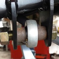
 
Not following. The mounts go where they need to go to create the desired relationships.

Preserving caster throughout the suspension travel is nice because the handling doesn't change when you are barreling down the trail at a high rate of speed. The pinion is going to be fine because it isn't going to exceed it's range of motion, unless things are poorly setup or you have some ridiculous amount of shock travel.
The minimal caster change is nice on the trails but this is why I do it.
DSC_4931.webp
 
  • Like
Reactions: jjvw
my non important point was i said pinion angle, while y'all said castor was what y'all were attempting to retain trough travel.
since the castor to pinion relationship is dictated if you controlled your castor you also controlled the pinion.
either way you go at this it's boils down to minimizing axle roll through the travel arc.

sorry, i did not mean to mistake your words with my interpretation.

this was over a yr ago and my CRS is horrible but IIRC.
i ended up at about -2.2* at my stuffed position and +2.3* at full droop. not being willing to drop the lower anymore and not having your BL height, keeps me from parallel links.
now. i can take and shorten the travel distance to -3.5" to +3.5" (the most used zone of our suspension) within those parameters the axle movement is down to .075* up and .080* drooped, so the more extreme angular change is on the end of my travel arcs the middle is not as drastic.
 
We're you able to determine anything from your model? I was going to tack my "like stock" brackets in different positions to see what the results would be. That be based on if I have time or not. It'd probably be easier to make a cardboard sample and do it that way. Then I could draw lines of travel and compare the difference. I know I wouldn't be the first to do this but it would be interesting to see the results.
making any headway?
 
No, I had to go back to work for the last two days... Head out to lake McConaughy until Tuesday. I'll get after it then. My guess is that I'm probably over thinking it. I've been looking at a link calculator to see what I can come up with.
 
No, I had to go back to work for the last two days... Head out to lake McConaughy until Tuesday. I'll get after it then. My guess is that I'm probably over thinking it. I've been looking at a link calculator to see what I can come up with.
I'm interested to see what you come up with. I'm in the same situation right now.
 
it can be daunting.

maybe consider mimicking the lower brackets (add pinion rotation in the rear if needed). down is the wrong direction for clearance and up squeezes your upper vs lower spread.
if your going to a truss for the uppers, that'll handle the range for 35's at about 8.75-9" of vertical separation off a stock lower

i carry 9" on my front axle and 8" on my frame end. until it gets properly tested i'm really not positive what i've created.
i'm thinking about 9"axle and 6-7" on the frame for the rear. i'm just starting into it.
 
I'm going to tack my brackets in place and then adjust the links to parallel and see how far the bolt hole moves (just out of curiosity). Then I'll run it up to full bump and down to full droop with an angle finder on the front. I was just curious of why Jeep did it that way.
 
I think Jake does a great job explaining what we are trying to figure out. I'm not 100% sure how this will apply to what I'm trying to do just yet, but it's a good education on how anti-squat and anti-dive numbers will affect the result you are looking for. At one point he puts the cardboard links in his simulator at the same frame point which caused the pinion to maintain the same angle with the links the same length. (12:50). I really want to make a template like that and play around with it to see what happens. I'll probably still end up on a relatively stock mount location in the end but it is really intriguing to me lol.

 
Last edited: