Cold Air Intake
I've been following the various threads on CAI systems for a long time. Many "CAI" systems are actually Hot Air Intake systems, with an easy-breathing but lousy filter. They try to boost horsepower by getting more air into the engine. I'm not shooting for more horsepower. The stock 4L engine can already breathe adequately. I'm just shooting for a simple, low-cost, true Cold Air Intake system.
According to some of the recent tests and discussions, I can expect to lose less power under heavy load in hot conditions, where the PCM senses a high intake temperature and backs off the ignition timing.
There is some discussion about this in Jezza's Dyno Testing Bolt-ons On The 4.0 series (page 5, 7). And later, in Jezza's Windstar Cold Air Intake video, a less restrictive intake system, along with a true Cold air intake, shows a reduction in intake temperature, an advance in ignition timing, and additional horsepower. It is unclear whether the true-CAI or the larger duct and air cleaner made the biggest contribution.
A recent discussion on Steel City 06's Installing an Ecoboost Oil Cooler (page 1, 2, 6, 7) also happens to explain some things about cold air intakes and insulated intake ducts. The CAI stuff is scattered throughout the thread, but it talks about oil, coolant, and air temperature effecting how the PCM pulls timing.
@NashvilleTJ demonstrates this nicely over here.
By drawing in cooler air, you may reduce the spark retard (PCM trying to prevent pre-detonation / ping / spark knock). And you'll get a little denser air. That doesn't necessarily give you more power than stock (although you might see some gain), but it could let you keep the stock power (say, pulling a trailer over a mountain pass, at low speed, low airflow, hot day) instead of having the PCM backing off the spark advance just when you need all of the power you can get.
I removed the little snorkel from the air cleaner box. With the air cleaner box removed, the snorkel twists counter-clockwise and pulls out.
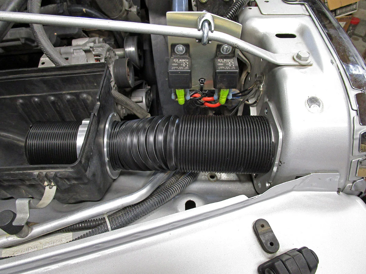
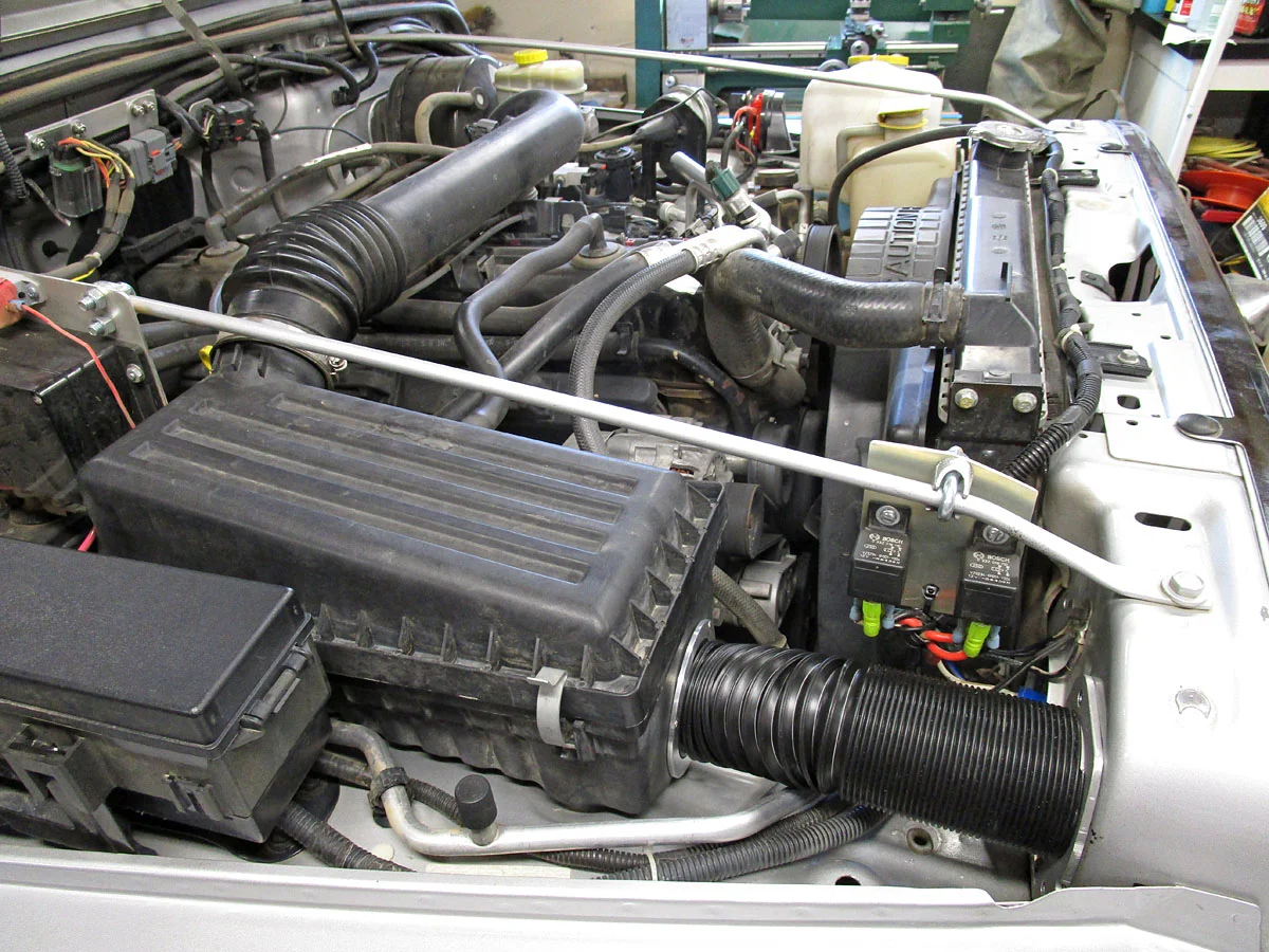
My CAI system will take in air through the existing rounded-square hole in the back of the grille, behind the right headlight.
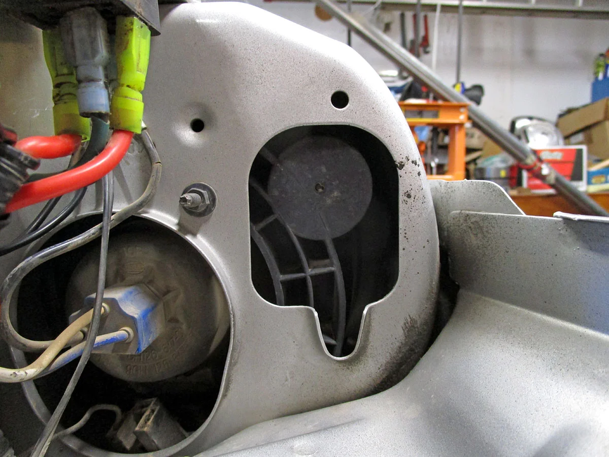
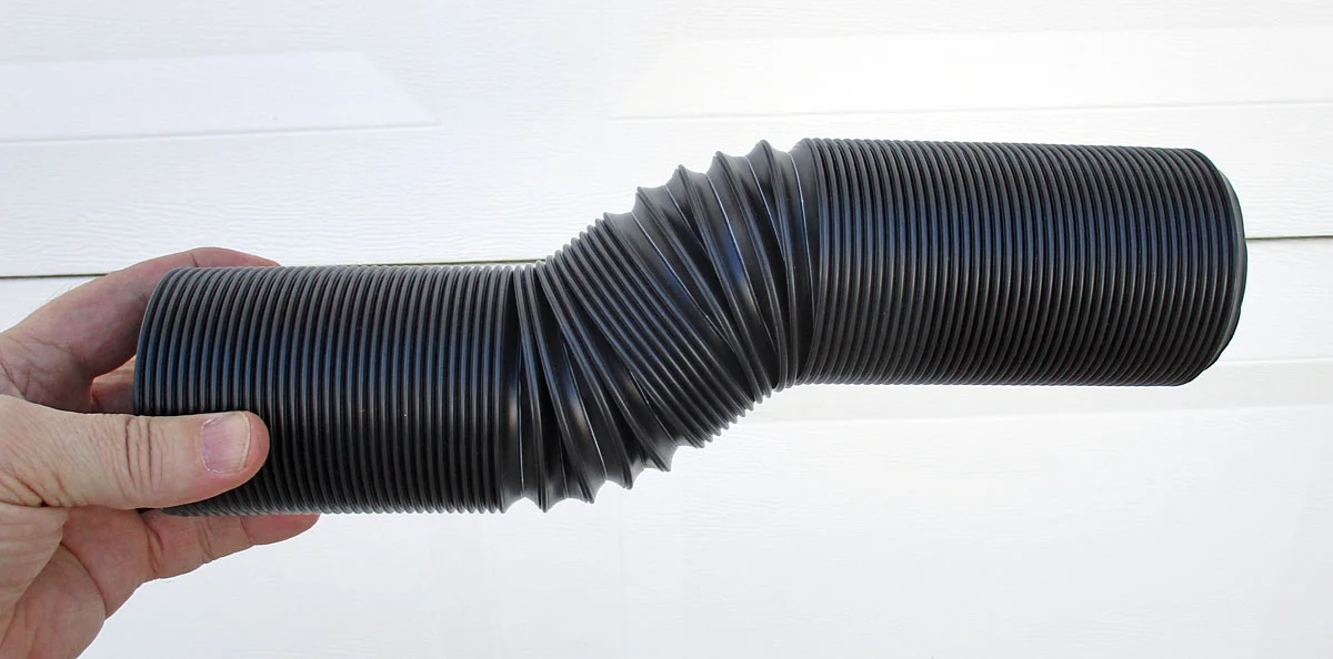
It will use a 2.5" ID flexible duct ($15.99).
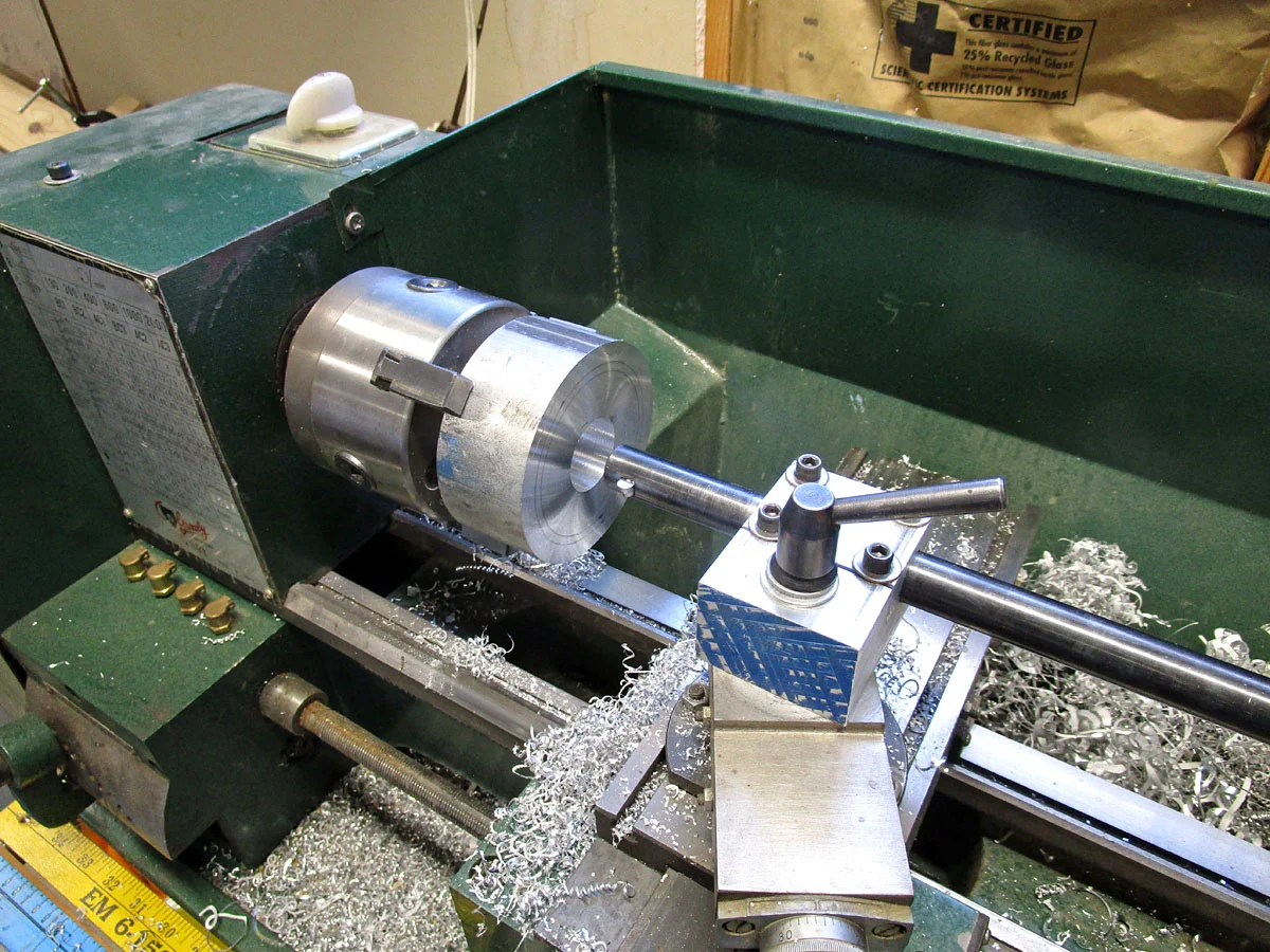
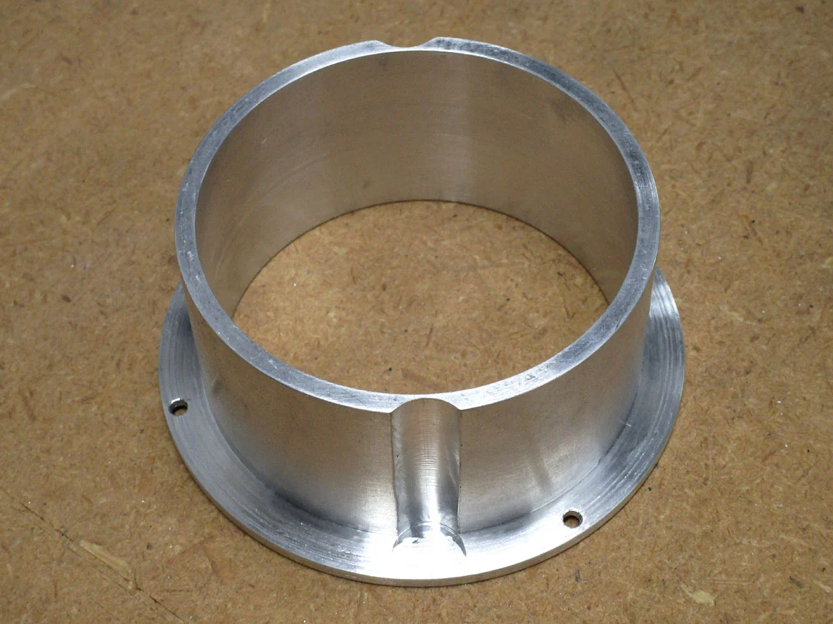
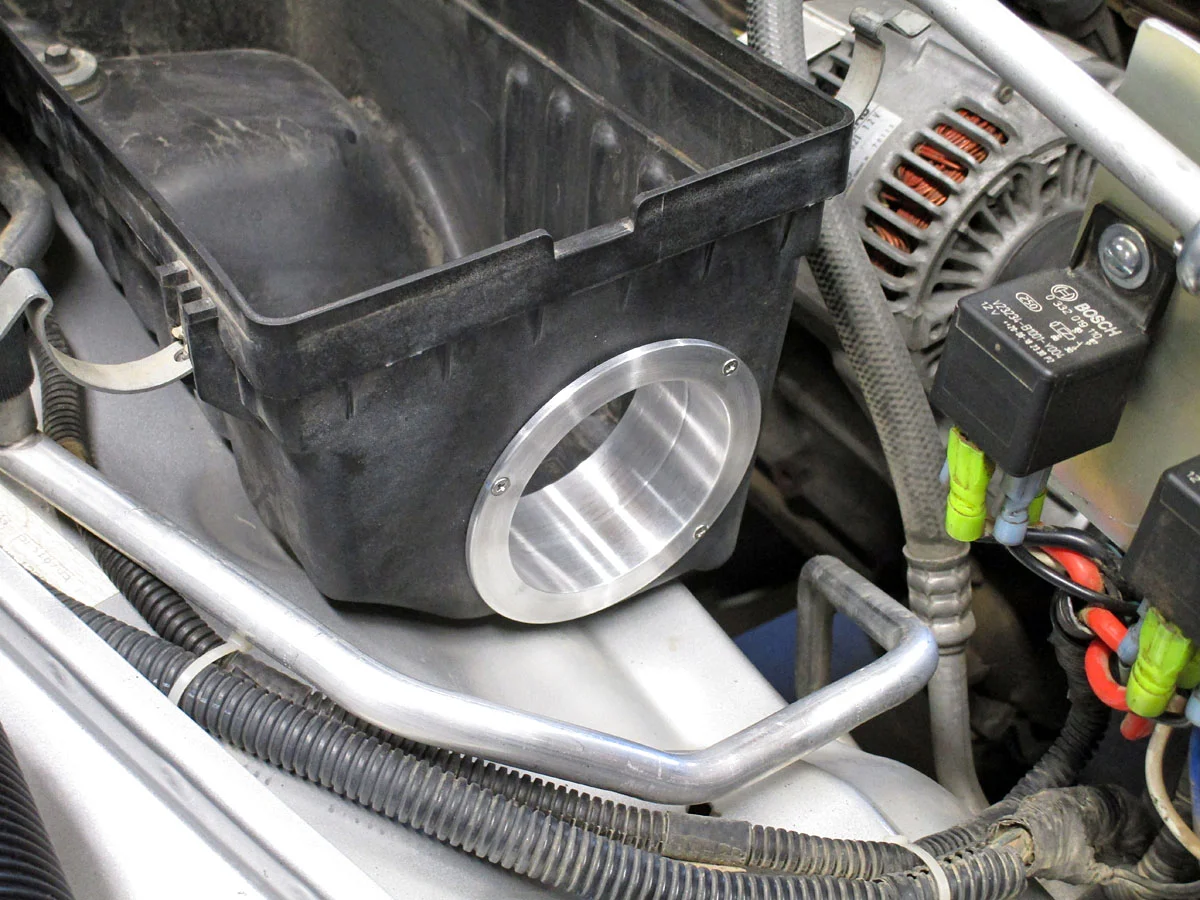
I made a couple of flanges to attach the duct. For the air cleaner box flange, I turned a scrap aluminum billet on a lathe. The flange is cut to fit the keyed hole in the airbox, and held in place with three #4-40 screws/nuts (with Loctite blue 243). The duct slides through it.
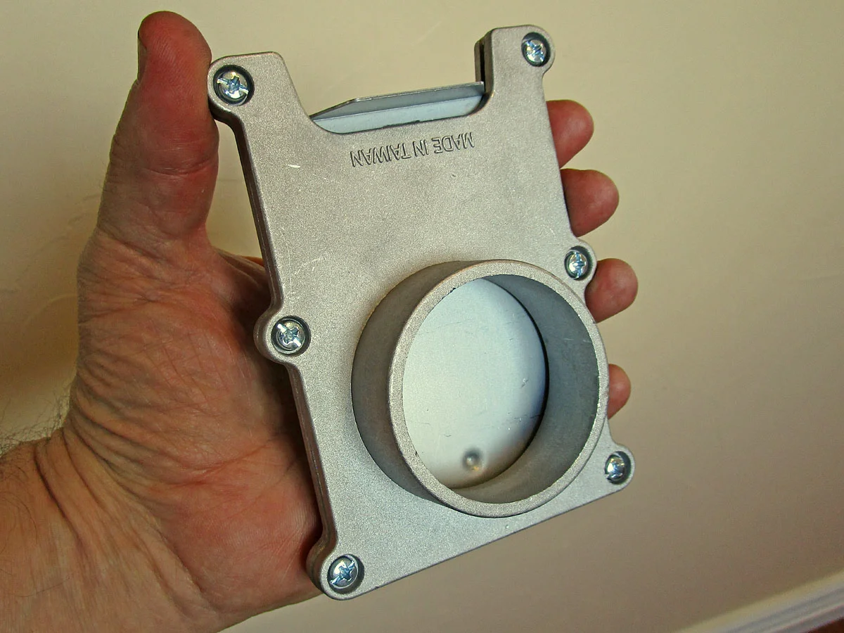
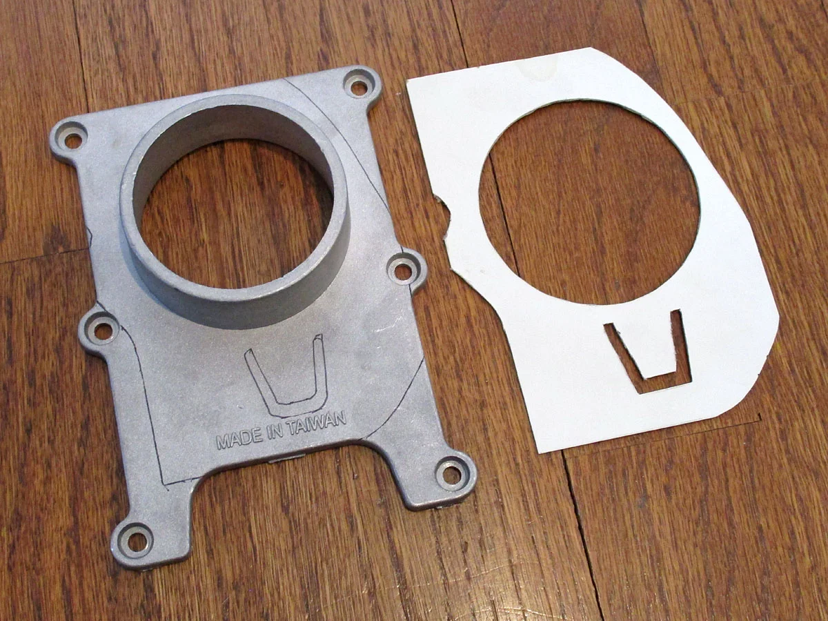
For the grille flange, I used an aluminum blast gate ($10). I made a paper template on the grille, and then cut and filed the blast plate into a flange. I attached the flange to the grill with three #8-32 screws/nuts (with Loctite blue 243).
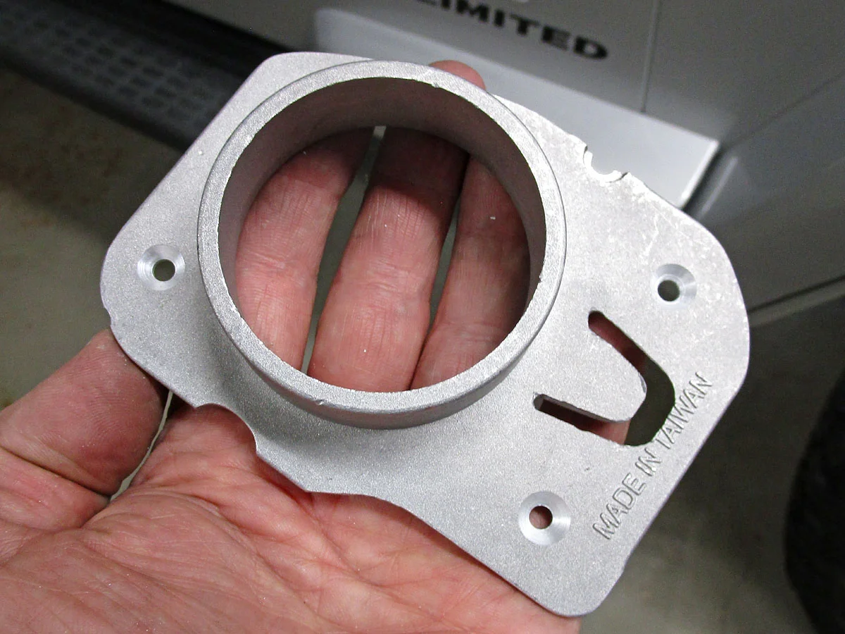
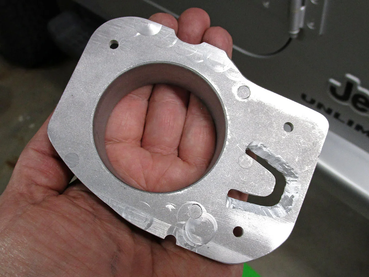
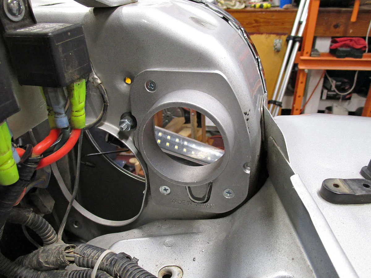
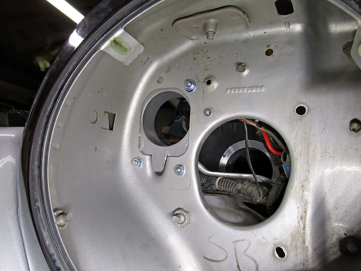
Note: I think both of these flanges could be 3D printed pretty easily.
The duct can be bent, and holds its shape quite well. It just slides into the air cleaner box flange, and over the grille flange. It's stiff and snug enough that I didn't use a clamp. The duct extends a few inches inside the air cleaner box, similar to the way the OEM snorkel did.
There are several openings into the headlight cell in the grille. In order to get mostly outside air, I blocked the holes from the engine compartment.
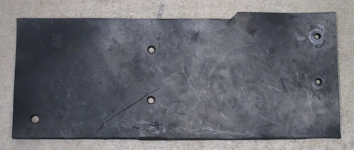
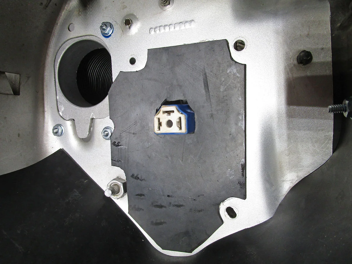
For the several holes near the bottom, I cut a baffle from 1/8" thick rubber. It hangs on one of the fender bolts, with two #10-24 screws through the rubber divider next to the radiator. It's snug against the front and rear of the grille, which helps hold it in place and seal fairly well. It has a couple of drain holes at its lowest point.
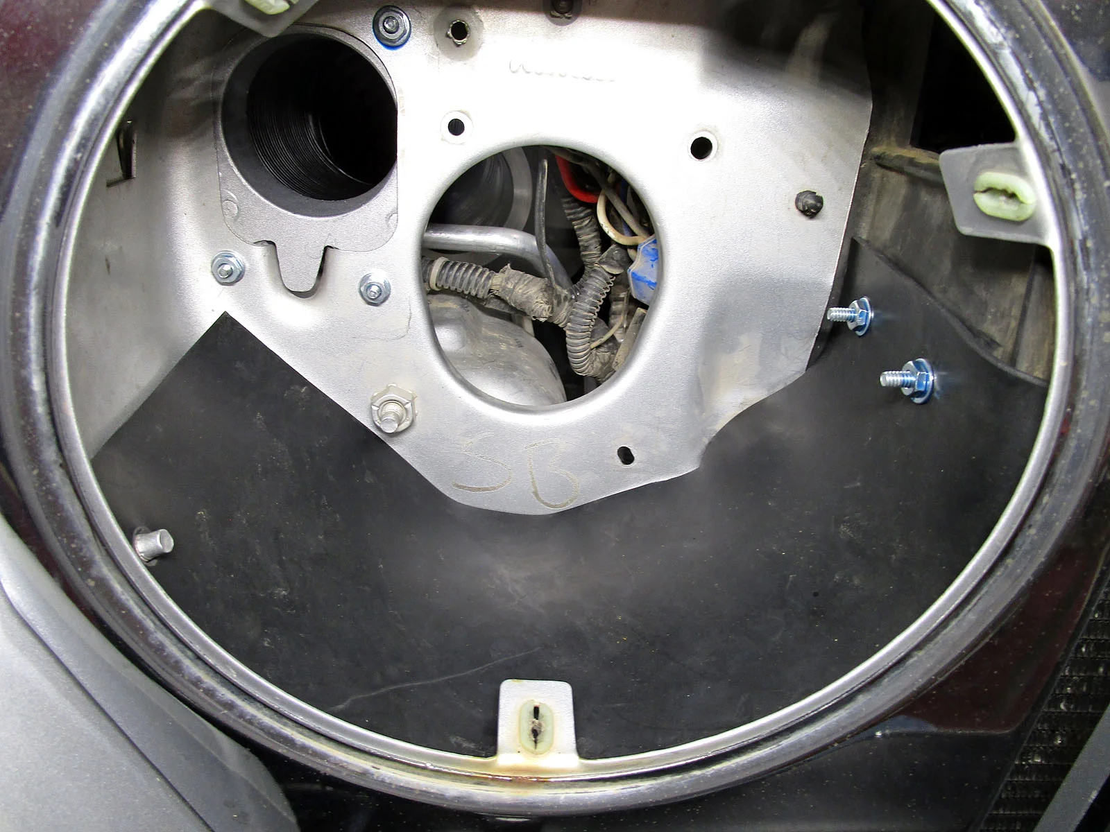
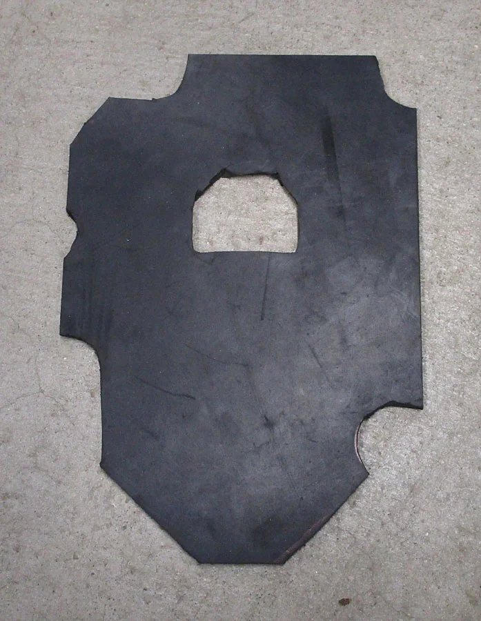
For the oval hole behind the headlight, I cut another rubber baffle with a hole for the headlight connector, and glued it in place with silicone sealer.
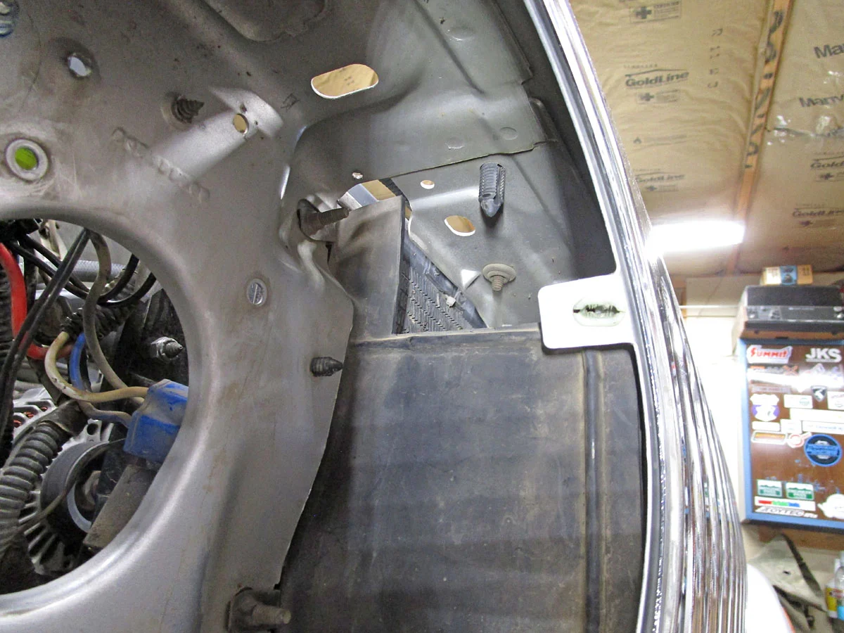
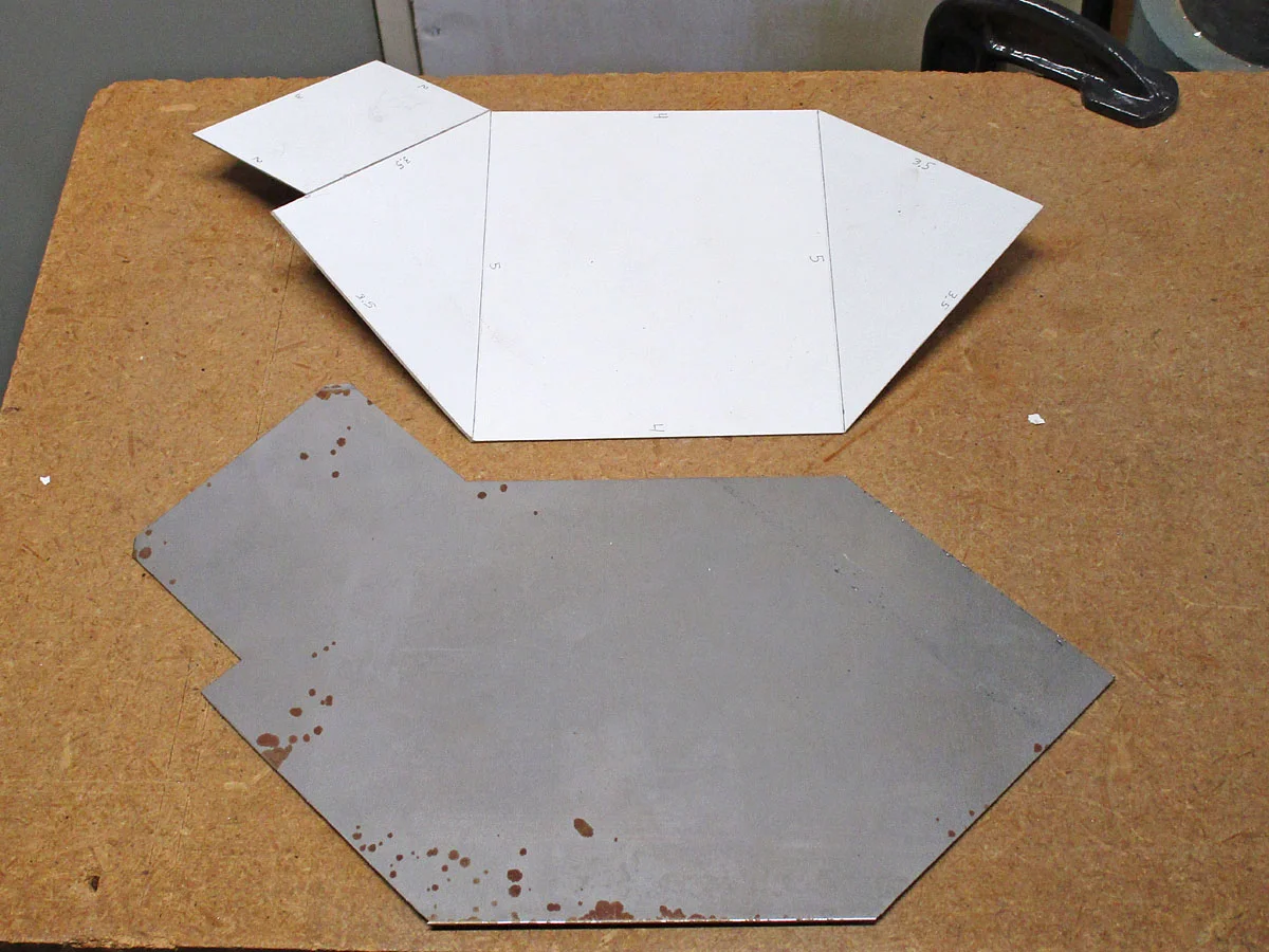
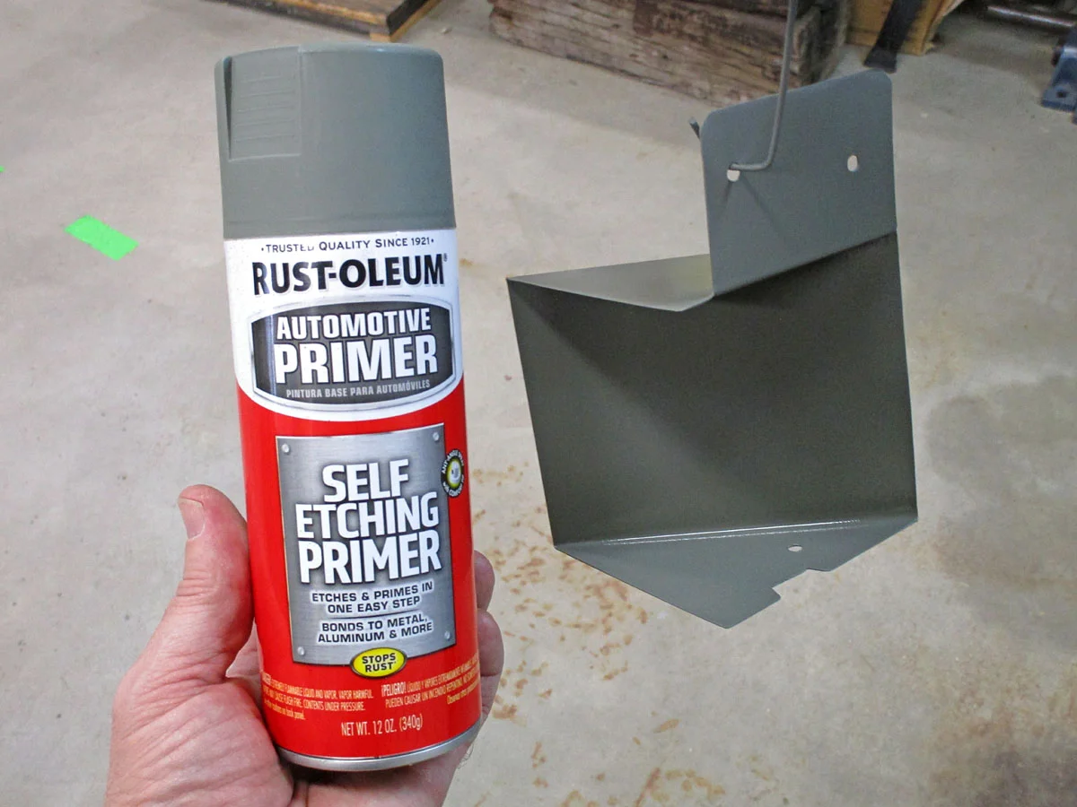
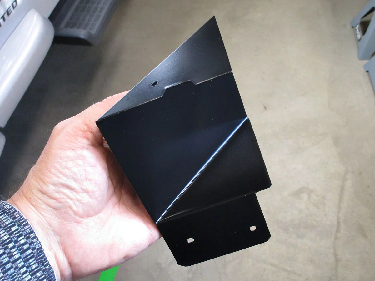
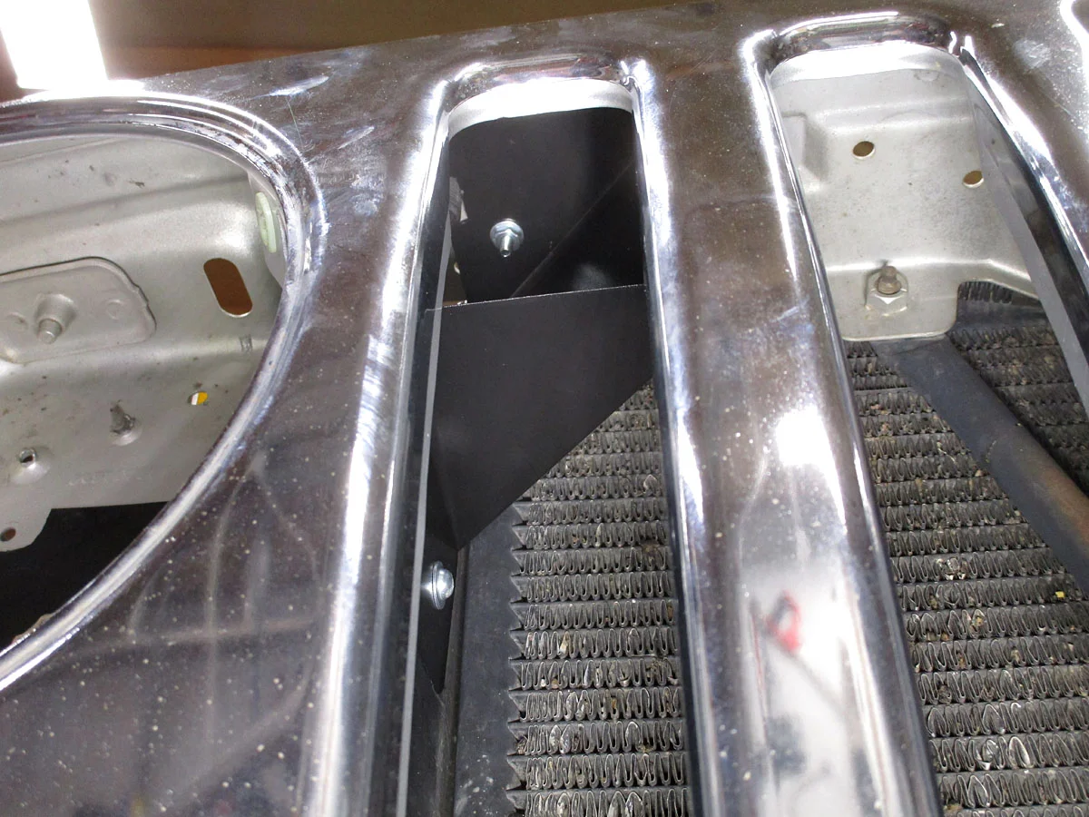
I cut a new opening in the top of the rubber divider between the headlight cell and the radiator to allow outside air from in front of the radiator to enter the headlight cell. I made a cardboard template for an air director, and tried it in place. Then I made an air director from 22 gauge steel, sanded, degreased, primed, painted, and baked it, and screwed it into place.
Initial results: With an outside temperature of 52°F, OBD-II reports an Intake Air Temperature of 64°F to 68°F (driving around town for 1/2 hour). An IR gun says the new duct is about 120°F (not running), with the airbox and crossover ducts even hotter.
I haven't done any real temperature testing yet, since it's cool outside (but the warmest, driest Colorado winter ever). Next summer I may temporarily revert it to take in underhood air, and collect intake air temperatures for the OEM setup and for the new CAI setup, while climbing the long uphill grade on I-70.
With the intake out in front of the grill, I can't hear any noise from it over the fan noise (unlike some of the cowl intake systems).
The whole thing:
Edited 2026/04/18 to add a reference to a @NashvilleTJ comment.
I've been following the various threads on CAI systems for a long time. Many "CAI" systems are actually Hot Air Intake systems, with an easy-breathing but lousy filter. They try to boost horsepower by getting more air into the engine. I'm not shooting for more horsepower. The stock 4L engine can already breathe adequately. I'm just shooting for a simple, low-cost, true Cold Air Intake system.
According to some of the recent tests and discussions, I can expect to lose less power under heavy load in hot conditions, where the PCM senses a high intake temperature and backs off the ignition timing.
There is some discussion about this in Jezza's Dyno Testing Bolt-ons On The 4.0 series (page 5, 7). And later, in Jezza's Windstar Cold Air Intake video, a less restrictive intake system, along with a true Cold air intake, shows a reduction in intake temperature, an advance in ignition timing, and additional horsepower. It is unclear whether the true-CAI or the larger duct and air cleaner made the biggest contribution.
A recent discussion on Steel City 06's Installing an Ecoboost Oil Cooler (page 1, 2, 6, 7) also happens to explain some things about cold air intakes and insulated intake ducts. The CAI stuff is scattered throughout the thread, but it talks about oil, coolant, and air temperature effecting how the PCM pulls timing.
@NashvilleTJ demonstrates this nicely over here.
By drawing in cooler air, you may reduce the spark retard (PCM trying to prevent pre-detonation / ping / spark knock). And you'll get a little denser air. That doesn't necessarily give you more power than stock (although you might see some gain), but it could let you keep the stock power (say, pulling a trailer over a mountain pass, at low speed, low airflow, hot day) instead of having the PCM backing off the spark advance just when you need all of the power you can get.
I removed the little snorkel from the air cleaner box. With the air cleaner box removed, the snorkel twists counter-clockwise and pulls out.
My CAI system will take in air through the existing rounded-square hole in the back of the grille, behind the right headlight.
It will use a 2.5" ID flexible duct ($15.99).
I made a couple of flanges to attach the duct. For the air cleaner box flange, I turned a scrap aluminum billet on a lathe. The flange is cut to fit the keyed hole in the airbox, and held in place with three #4-40 screws/nuts (with Loctite blue 243). The duct slides through it.
For the grille flange, I used an aluminum blast gate ($10). I made a paper template on the grille, and then cut and filed the blast plate into a flange. I attached the flange to the grill with three #8-32 screws/nuts (with Loctite blue 243).
Note: I think both of these flanges could be 3D printed pretty easily.
The duct can be bent, and holds its shape quite well. It just slides into the air cleaner box flange, and over the grille flange. It's stiff and snug enough that I didn't use a clamp. The duct extends a few inches inside the air cleaner box, similar to the way the OEM snorkel did.
There are several openings into the headlight cell in the grille. In order to get mostly outside air, I blocked the holes from the engine compartment.
For the several holes near the bottom, I cut a baffle from 1/8" thick rubber. It hangs on one of the fender bolts, with two #10-24 screws through the rubber divider next to the radiator. It's snug against the front and rear of the grille, which helps hold it in place and seal fairly well. It has a couple of drain holes at its lowest point.
For the oval hole behind the headlight, I cut another rubber baffle with a hole for the headlight connector, and glued it in place with silicone sealer.
I cut a new opening in the top of the rubber divider between the headlight cell and the radiator to allow outside air from in front of the radiator to enter the headlight cell. I made a cardboard template for an air director, and tried it in place. Then I made an air director from 22 gauge steel, sanded, degreased, primed, painted, and baked it, and screwed it into place.
Initial results: With an outside temperature of 52°F, OBD-II reports an Intake Air Temperature of 64°F to 68°F (driving around town for 1/2 hour). An IR gun says the new duct is about 120°F (not running), with the airbox and crossover ducts even hotter.
I haven't done any real temperature testing yet, since it's cool outside (but the warmest, driest Colorado winter ever). Next summer I may temporarily revert it to take in underhood air, and collect intake air temperatures for the OEM setup and for the new CAI setup, while climbing the long uphill grade on I-70.
With the intake out in front of the grill, I can't hear any noise from it over the fan noise (unlike some of the cowl intake systems).
The whole thing:
Edited 2026/04/18 to add a reference to a @NashvilleTJ comment.
Last edited:



 Even with the camera tilted down at 37° from level, I can only see things on the ground to within 30" behind the spare tire. For comparison, my wife's Subaru camera, at the same height and down-angle, can see stuff to within 8" of the rear bumper.