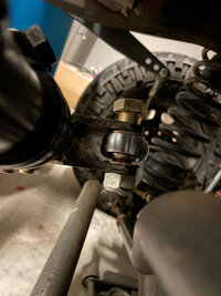
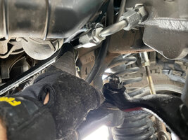
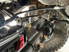
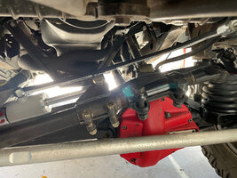
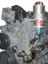
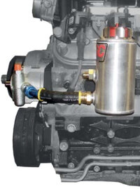
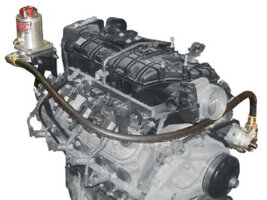
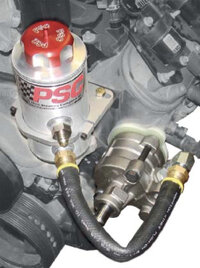
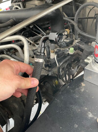
PSC Hydro-Assist Installation Instructions (Using Black Magic Kit)

Chris

Administrator
Staff Member
Ride of the Month Winner
Joined
Sep 28, 2015
Messages
71,098
Location
Gillette, WY
First and foremost, thanks to Blaine for making this happen. Additional thanks goes out to @toximus for helping to improve this write-up.

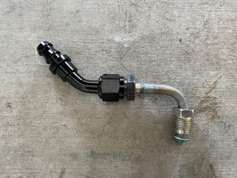
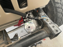
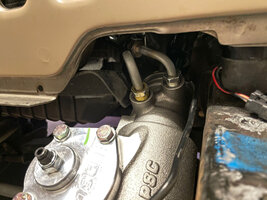
This thread is to serve as the official installation instructions for the Black Magic nearly bolt-in PSC hydro assist kit for Currie steering. This kit assumes that you have the Currie steering and that you've pieced together the other remaining parts you'll need from PSC. Take your time installing the hydro-assist. While it's not overly difficult, there are a lot of small things to pay attention to to ensure a proper installation.


Parts needed from PSC to complete the install
  • PSC steering gearbox (new, not reman)
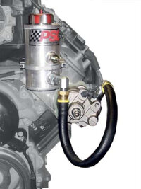
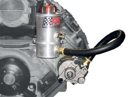
  • PSC remote reservoir with -12 outlet and -8 return
  • PSC CBR pump with -12 inlet
  • -12 45° and 90° fittings
  • -12 hose (14-18")
  • Positive pressure check valve

Other parts needed to complete the install
If you have a 2003-2006 TJ you may consider using a lower steering shaft from a 97-02 TJ instead of the common shortening of the 03-06 shaft. The PSC steering gear is the same body size as the 97-02 which makes it longer than the 03-06. The shortened shaft method develops slap in the slip section on some.

You'll also need a class 8.8 M8x1.25 25mm length bolt.

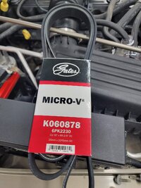
Finally, 03-06 automatic models with AC need a belt size one smaller because PSC's CBR pump comes with a slightly smaller pulley. K060878 is the right belt.
20220806_174437.jpg


Tools needed for install

Important Installation Notes
  • Park the Jeep with the wheels straight. This is so that the steering wheel will be centered when you strap in the steering wheel to prevent it from damaging the clock spring.
  • All low pressure hoses are push lock. Low pressure hoses go on the return side (or everything after the steering gear through the cooler back to the reservoir). All low pressure hoses also get Oetiker clamps.
  • High pressure hoses all use the screw together field serviceable ends. All the high pressure stuff is -6 including the 3/8" OEM power steering hose from the pump to the steering gear inlet side.
  • All fittings with threads either straight or tapered get red liquid Loctite at the following locations:
    • -8 return adapters into each end of the cooler. Just the adapter, not the push lock fitting that goes into the hose.
    • -12 male into the reservoir for the feed hose to the pump. It is O-ring Boss or straight threads with an o-ring. It will seep fluid and back out when you try to remove the flare fitting from it if you don't use red Loctite on it.
    • -8 male return from cooler same thing. ORB, will seep and loosen without red Loctite.
  • Only low pressure hoses get Oetiker clamps. Low pressure hoses are everything after the steering gearbox, through the cooler, and back to the reservoir.

Layout & Routing Diagram
Please pay close attention to this diagram I've made. This is the layout for all the parts in the kit, where they go, and the routing for all the hoses. This diagram alone should take nearly all the guess work out of the installation, so it's imperative that you study and understand it. Each part is labeled with a number which I will reference throughout the instructions.

Click to enlarge image

Diagram.jpg


Part index
Parts listed below in red need to be purchased directly from PSC (they are mentioned and linked to at the beginning of these instructions). The parts in black are the ones that come in the Black Magic nearly bolt-in PSC hydro assist kit for Currie steering. Parts 1-2 are in the check valve kit. 3-Reservoir mounting bracket is not used but is included with reservoir. 3-7 are included with the reservoir.
  1. Positive pressure check valve
  2. Positive pressure check valve line and fitting
  3. Reservoir mounting bracket
  4. PSC remote reservoir with -12 outlet and -8 return
  5. Auxiliary port plug
  6. -8 return adapter
  7. -12 male adapter
  8. -12 90° fitting
  9. -12 hose
  10. -12 45° fitting
  11. PSC CBR pump with -12 inlet, OEM style outlet
  12. 3/8" OEM power steering hose
  13. PSC steering gearbox
  14. -6 field serviceable high pressure hose end (4)
  15. -6 high pressure hose
  16. Modified assist cylinder
  17. Draglink clamp
  18. Cylinder bolt
  19. Clamp pinch bolt (2)
  20. Stabilizer / track bar mount reinforcement plate
  21. Cylinder mount
  22. 1/2" cylinder bolt
  23. 3/8" cylinder mount tie-in bolt
  24. Misalignment spacers
  25. Cylinder mount spacer
  26. Cylinder mount tie-in spacer
  27. Cylinder mount axle clamp
  28. -8 male return adapter
  29. -8 45° push lock
  30. -8 low pressure push lock hose
  31. -8 90° push lock (3)
  32. -8 x 3/8" NPT adapter (2)
  33. Cooler mount
  34. Heat sink cooler
  35. Cooler stud plate with hardware (2)
  36. Cooler mount to v-bar capture brackets (2)

Installation Instructions
See below for step-by-step instructions. Click here if you'd like a copy of the instructions in PDF format so you can print them out and take them to the garage with you.
 

Attachments

  • PSC Hydro-Assist Installation Instructions (Using Black Magic Kit).pdf
    1.9 MB · Views: 304
Step 1

1) Remove the front bumper completely.
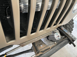
2) Disconnect the anti-sway bar if it's in the way of the steering gear bolts.

20220806_210342.jpg
 
  • Like
Reactions: Lax22
Step 2
Remove the pitman arm from the steering gear. I used my electric impact and a 33mm impact socket or a 1 5/16" socket to remove the nut that holds the pitman arm to the steering box. Note that after doing this the pitman arm will not come off with your hands. You're going to need a pitman arm puller to easily remove the pitman arm from the steering box. There are other ways to do it, but this is the easiest and most hassle free way that won't leave you frustrated and cursing. :)

5.jpg

6.jpg
 
Step 3
Start by draining the fluid from the power steering system. I did this by loosening these two fittings on the steering box and the cap on the reservoir:

1.jpg

I put a drip pan below the steering box, loosened and removed the fittings, and then waited for the system to drain out. Note that even after doing this there will still be fluid that comes out as you remove other pieces of the system, but this should at least get the bulk of the fluid out.

4.jpg
 
Step 4
After removing the serpentine belt I went ahead and removed the power steering pump.

Start by removing the hard line that goes from the power steering pump to the gearbox with a line or open end wrench. Loosen the fitting at the power steering pump, then loosen the fitting at the steering gearbox (which you should have done in step 2 anyways to drain the fluid). Get the hose out of the way now and then proceed to remove the pump.

The pump is attached with three long bolts. To remove each bolt you have to rotate the pulley so that a hole in the pulley is aligned with the bolt behind it. Once you do this you can easily fit your socket, extension, and ratchet in and remove each bolt, one-by-one like so:

2.jpg

Pump removed.

3.jpg
 
  • Like
Reactions: Lax22
Step 5
Once the fluid was done draining I started by removing the serpentine belt from the system. This is done with a 1/2" breaker bar, insert the square end into the square hole in the belt tensioner and rotate tensioner to release the tension on the belt. Hold the tensioner and then remove the serpentine belt from one the pulleys. Pay attention to the routing before the belt is removed if the diagram on the radiator is missing.

If you have the 97-99, the steering pump is the serpentine tensioner and will have to be dealt with accordingly.
 
Step 6
To remove the steering box, the steering shaft needs to be removed from the input shaft on the steering gear. Take out the bolt in the pinch clamp, slightly spread the split open and remove the shaft. After you turn the steering wheel to position the bolt in such a way that you can either remove it from the top side or the bottom side, lock the steering wheel to the brake pedal or similar with a bungee cord to prevent full rotation of the steering wheel. If you turn the steering wheel with it disconnected from the steering gear, it will break the clock spring.

7.jpg

Once the bolt is removed, I used a pry bar to pry the steering shaft back enough so that it would slide off the splines. The pry bar helped a lot since the shaft is stuck on there pretty good from all the years of never having been removed.

Now you'll want to remove the three bolts that hold the steering box to the frame rail:

8.jpg

Make sure to hold the steering box from underneath, as once you get to the last bolt it will fall to the ground and it's very, very heavy!

9.jpg
 
  • Like
Reactions: Sudo and Lax22
Step 7
Next up I decided to install the cooler behind the grille. This is a way to do it. If you have the condenser and radiator out for any reason, that works too.

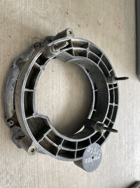
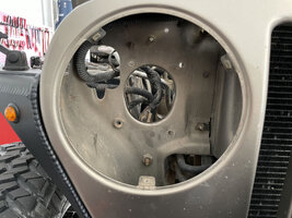
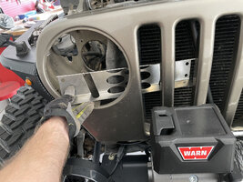
To start with you'll need to remove the passenger headlight and headlight bucket. It isn't necessary to remove the headlight from the bucket. Remove the headlight bezel, unplug the connector off of the head lamp, and then remove the 3 nuts from the studs on the engine side of the grill shell. That allows the assembly to come out through the headlight hole and the lamp doesn't have to be reinstalled back into the bucket.

Here is the headlight bucket removed. You can see how it attaches from inside the engine bay using three 10mm nuts: I opted to pull the lamp and bucket separately.

10.jpg

Once removed, your passenger headlight will look like this:

11.jpg

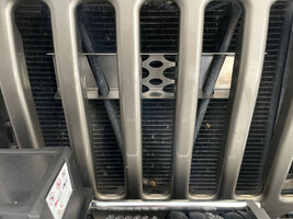
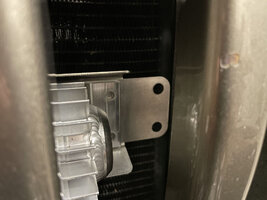
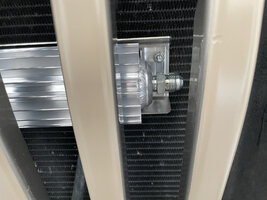
Now that the headlight bucket is removed, you can slide the cooler mount (part number 33 in the diagram) in through the headlight and onto the v-bar support like so:

12.jpg

13.jpg

Unfortunately the cooler itself can't slide in as easily from the headlight without pushing the radiator back some.

To do this you need to unbolt the radiator fan shroud from the flanges on the radiator. After that is pulled and set back towards the engine, then the radiator needs to be unbolted from the grill. Loosen the bottom two several turns but do not remove. Then remove the remaining two on each side (some later ones only have one left on each side)

Leave the radiator sitting on the bottom two bolts. The condenser bolts in the two tabs the point forward on top of the grill will need to come out so the radiator and condenser can be wedged back at the top to create some room inside the grill.

The trick here will be pushing the top side of the radiator back as far as you comfortable can, while sliding the cooler (part number 34 in the diagram) in through the passenger headlight. Believe me when I say it's tight, but it will fit. You can make it easier if you have someone help you to hold back the radiator while you guide the cooler in through the headlight. I did it all by myself and it was tricky, but I managed to do it.

14.jpg

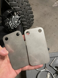
Now you'll need these cooler mount to v-bar capture brackets (part number 36 in the diagram) to securely fasten the cooler and cooler mount onto the v-bar.

15.jpg

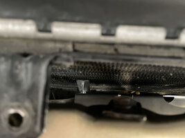
This is done by sliding the brackets between the cooler and the mount like so making sure they go behind the V bar tube but in front of the back face of the cooler:

16.jpg

What this does is capture the v-bar from the backside so that the cooler will be securely fastened in place.

NOTE: If you have a "medium" diameter V bar, hose is too thick, instead, bend the brackets slightly before sliding them in to apply pressure against the V bar when they are tightened.

20220806_133121.jpg

Once the brackets are in place, reach down from the top side and put the stud plates (part number 35 in the diagram) in through the backside of the cooler mount, then tighten the nuts down from the front. The nut and stud plate are not doing anything but stopping the tab from falling out. No need to overtighten them and break the studs off. Blaine has more and will help you out but not without lots of abuse for being silly.

19.jpg

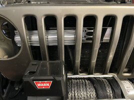
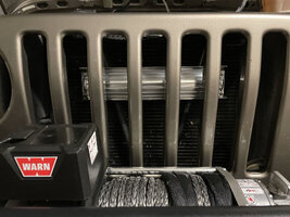
This will be the end result:

17.jpg

While you're installing the cooler, now is a perfect time to install the -8 x 3/8" NPT adapters (part number 32 in the diagram) onto each end of the cooler. As mentioned in the important installation notes above, these adapters will need Red Liquid Loctite on the ends that go into the cooler only.

After applying the Loctite, thread an adapter into each end of the cooler and use your wrench to tighten it down a full turn past hand tight.

18.jpg
 
  • Like
Reactions: Lax22
Step 8 (for 03-06 TJs only)
This step only applies to 03-06 TJs and involves installing the lower steering shaft from a 97-02 TJ in place of your factory steering shaft. While you can modify your 03-06 steering shaft to fit, I'm convinced it's not worth the effort when you account for the cost of a new 97-02 steering shaft.

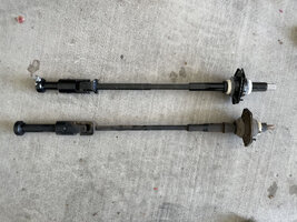
Looking at the photo below, you'll see why we need to install the 97-02 shaft on our 03-06 TJs:

20.jpg

In that photo, the 97-02 steering shaft is on top, and the 03-06 steering shaft is on bottom. The longer section that connects to the steering gear input shaft is the problem. The PSC gear is based on the early Saginaw steering gear which is longer and needs the shorter section to keep the steering shaft angles correct.

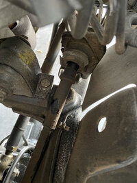
To remove the steering shaft at this point is very easy. You'll need a deep socket to remove the two bolts holding the steering shaft to it's bracket which you can see in this photo:

21.jpg

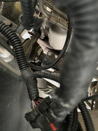
You'll also need to loosen this larger bolt in the clamp and holds the end of the lower steering shaft into the upper steering shaft:

22.jpg

Once all the bolts were removed, my pry bar came in handy again to give the lower steering shaft a good nudge in separating it from the upper steering shaft. If it's never been removed before, it can be in there pretty good.

Now that you have the old 03-06 shaft out, install the new 97-02 shaft in it's place. Everything is keyed the same so there is no danger of getting anything out of alignment regarding the orientation of the steering wheel.
 
Step 9
It's time now to install the new PSC steering box.

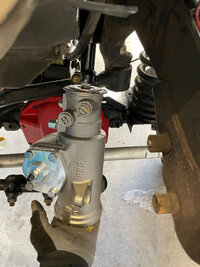
The first thing I did was attach the lower steering shaft to the splines on the steering gear box. Make sure to tighten the bolt down.

23.jpg

Now raise the steering box up and use the three bolts to attach it to the frame, making sure to torque them all to 70 ft/lbs.

24.jpg

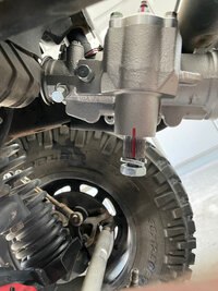
Be aware that the red lines on the steering gearbox and the steering shaft need to be aligned. This is how you know the steering box is centered. If they are not aligned, you will have issues with your steering.

25.jpg
 
  • Like
Reactions: Chasitek and Lax22
Step 10
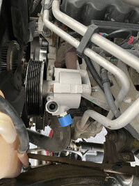
Next you'll want to install the new PSC pump (part number 11 in the diagram). Installation is the opposite of removal. There are three bolts holding it on. Different from the OEM pump, the CBR power steering pump has 2 through holes for the OEM mounting bolts to be reused and 1 threaded hole. In that threaded mounting hole, a class 8.8 M8x1.25 25mm length bolt is needed.

IMG_9431.jpg
 
Step 11
After installing the new PSC pump, you'll want to install the OEM power steering line (part number 12 in the diagram). This line is a hard line and is pre-formed, so there is only one way you can install it.

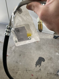
Notice that the hose has a baggie attached to it with two o-rings in it. It is absolutely imperative that you install these o-rings on both ends, otherwise your system will leak.

IMG_9490.jpg

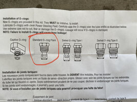
In the bag there are instructions which show how the o-rings need to be installed on this type of fitting:

IMG_9497.jpg

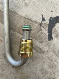
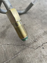
I dipped my finger in the Swepco power steering fluid, used that to lubricate the o-rings, then installed them as shown below:

IMG_9498.jpg

IMG_9499.jpg

Install the hose at the pump as shown below:

IMG_9500.jpg

Screw in the fitting at the steering gear but leave it a little loose so the hard line can rotate. Now insert a pry bar or long screw driver and clock the tubing so that it comes off the steering gear pointed toward the center of the Jeep. This will give the other fitting more room to point where it should.

20220806_164259.jpg

Tighten both fittings just past hand tight.
 
  • Like
Reactions: Lax22
Step 12
Once you've installed the hose, you can now move on to getting the power steering cooler hoses routed and installed.

I started doing this by attaching one of the -8 90° push lock fittings (part number 31 in the diagram) to the -8 low pressure push lock hose (part number 30 in the diagram). The trick to getting these fittings installed in the hose easily is to apply a thin layer of Swepco power steering fluid to your finger and coat the barbed end of the fitting. Doing this I was able to work the fitting into the hose with nothing more than a little hand strength. Finally, you'll need to install an Oetiker clamp (included with your kit) on the fitting to secure it in place as shown below:

IMG_9520.jpg

IMG_9512.jpg

Don't install a fitting on the other end just yet and don't cut the hose either. Install the end with the fitting onto the passenger side of the cooler. Tighten the fitting snug to the adapter on the cooler, then run the hose down and under the cooler, back to the drivers side and out through the bottom of the grille right next to where the steering gearbox is:

IMG_9513.jpg

You can now cut the extra hose off as we know how long it needs to be.

Next you're going to attach the -8 45° push lock and -8 male return adapter (part number 28 and 29 from the diagram) so that they look like this:

IMG_9515.jpg

Make 100% certain there is an o-ring on the end of the -8 male return adapter (part number 28 in the diagram)!

Slide an Oetiker clamp over the end of the hose, lube the barbed end of the push lock fitting, and then insert it into the hose as shown:

IMG_9516.jpg

Tighten the Oetiker clamp but lead the two fittings slightly loose as you'll need to play around with the correct angle for the fittings before tightening them down.

Route the hose down through the grille to the steering gearbox like so:

IMG_9514.jpg

This part was a bit tricky as there isn't tons of room in here, but I was able to get the fittings positioned in such a way that they cleared the radiator and the grill. The end result should look similar to this:

IMG_9524.jpg

It should go without saying that this line goes into the port on the steering gearbox that is closest to the driver. Once you have installed it, tighten it down.
 
  • Like
Reactions: Lax22
Step 13
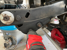
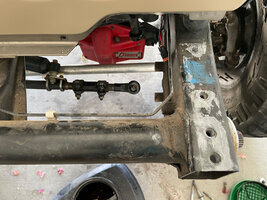
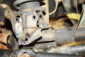
Next up you're going to want to install the cylinder mount brackets. These will strengthen the steering stabilizer brackets in order to accommodate the PSC hydro-assist cylinder.

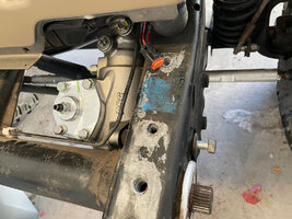
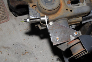
In order to install the brackets you're going to need to at least unbolt and drop the track bar from it's axle side mount. Once that is done, you can see in the photos below how the brackets get attached and where all the hardware goes.

20220806_202916.jpg

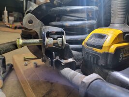
If the assist cylinder rod end with spacers don't fit in the OEM stabilizer bracket, you can widen the bracket by placing a bolt or all thread through with 2 nuts and use them to expand the area wide enough.

The rear bracket (number 23 in the diagram) bolts on the back side of the stabilizer mount, then the cylinder mount axle clamp (part number 29 in the diagram) or u-bolt goes around the bottom of the axle and bolts-in from the top of the mount.

1605626030725.jpg

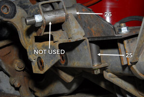
In this photo you'll see where the cylinder mount spacers go (parts 25 and 26 in the diagram). The spacer shown in the cylinder mount itself is not used and was only used for the purpose of putting things together. Use the vertical spacer to locate the hole that needs to be drilled for the 3/8" bolt.

1605626096128.jpg

The rear bracket (number 21 in the diagram) bolts on the back side of the stabilizer mount, then the cylinder mount axle clamp (part number 27 in the diagram) or u-bolt goes around the bottom of the axle and bolts-in from the top of the mount.

1605626341350.jpg

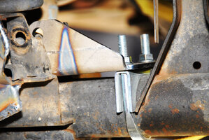
The stabilizer / track bar mount reinforcement plate (part number 20 in the diagram) gets welded in place as follows. At final install, get all the bolts, spacers, cylinder rod ends, in place before you tighten anything. Each mount seems to be slightly different so the parts will all have to be pulled together when everything is tightened. When locating the reinforcement plate for welding, use bolts in both holes to line them up. If one is slightly off, let the trackbar bolt be the priority and run a 1/2" drill bit through the hole for the cylinder.

1605626164085.jpg

The finished result will look like this.

1605626338012.jpg

Savvy Mid-Arm Addendum:​

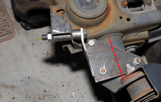
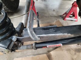
If you happen to have a Savvy mid-arm you'll find that the truss interferes with the rear bracket (number 21 in the diagram) so you'll have to cut a sizable portion off the bracket itself and then weld it directly to the truss. This means that the cylinder mount axle clamp (part number 27 in the diagram) or u-bolt won't be needed on mid-arm installs.

1605641169732.jpg

You will need a 1/4" thick 2"x7" piece of steel.

1) Create a cardboard template with a 1/2" hole on one end and shape it to avoid the suspension spring. Trace this onto the steel.

2) Cut out the steel into the shape of your template.

3) Put 2 bends in the steel roughly 45* angles so that it comes back flush with the mid-arm truss. Tip: If you don't have a press, you can place it in a vice and smack it with a hammer.

4) Bolt in your new bracket. To firmly place it against the truss, use a clamp with thick material on the backside so your clamp doesn't mar or dent the truss.

20220807_150716.jpg

5) Weld

20220807_154757.jpg

20220807_154819.jpg
 
  • Like
Reactions: Lax22
Step 14
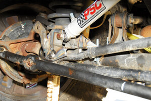
Now we are going to install the assist cylinder.

In preparation for this, I jacked the front end of the Jeep up, took both front wheels off, and put a jack stand on each side of the frame. I did this because you want the axle to hang down as low as it possibly could for the steps to come to make sure the hoses are long enough at full droop without any extra length. They need to be cut to a length has them stretched fairly tight at full droop without putting too much pressure on the fittings. If you get them too long, they can move back into the harmonic balancer and get damaged.

IMG_9567.jpg

Your drag link should still be hanging there as we have not yet bolted things back up. If you haven't already, you'll need to remove the drag link collar and tie-rod from the end. This is done so that we can slide the drag link clamp (part number 17 in the diagram) over the drag link itself.

To do this you'll need to grind the drag link round. While the drag link may appear to be round already, you'll notice there is a line going down the middle of it that is slightly raised. This needs to be ground down to allow the drag link clamp to slide over the drag link easier. Don't grind or sand away too much or the clamp will run out of adjustment when the pinch bolts are tightened. If that happens, take a cut off disc and enlarge the split in the clamp so there is a small gap when tightened.

Once this is done I put the drag link clamp on the drag link and used a pry bar to pry it open (so it would slide on the drag link easier) and then tapped it from the other end with a big hammer so that it would go on smoothly. This worked out well for me.

IMG_9506.jpg

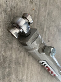
Next you'll want to get the cylinder assist (part number 16 in the diagram) and the two misalignment spacers (part number 24 in the diagram). Install the misalignment spacers onto the end of the cylinder assist like this:

IMG_9565.jpg

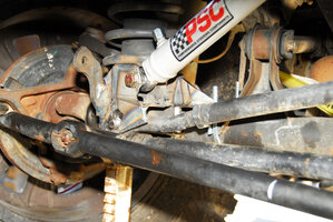
Now install the end of the cylinder assist in the axle side bracket like so.

To do this, you'll use the 1/2" cylinder bolt (part number 22 in the diagram), the two washers that go with it, and the nut. The aluminum spacer with the 1/2" hole in it goes between the back side of the stabilizer mount and the tab on the axle bracket.

1605626338012.jpg

Now we need to determine exactly where to position the drag link clamp on the drag link.

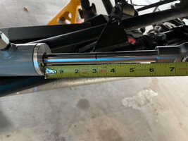
You want the cylinder assist to be in the middle of its travel when the wheels are straight. To do this we obviously make sure the wheels are straight first and then we fully extend the cylinder assist to its maximum travel.

If you take a measurement of the shaft when fully extended it will read exactly 6-1/8". Ignore the 1/8" as that is extra gap that is still there when it is fully compressed. Now mark the shaft with a pen exactly at the 3" mark.

Push the shaft back in until that 3" mark is barely visible. Your cylinder assist is now dead-center in the middle of it's travel.

IMG_9582.jpg

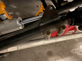
Now that the cylinder assist is in the center of it's travel, you can further position the drag link clamp into place so that it the holes align perfectly and you can get the bolt through.

IMG_9574.jpg

In order to get the bolt through the hole and things fitting perfectly, you're going to need to use the two cylinder clamp pinch bolts (part number 19 from the diagram) to clamp the bracket down. This will cause the bracket to spread open more, allowing you to insert the cylinder assist end easier into the bracket and get the bolt through. The washers go inside the tabs to add a small bit of misalignment to keep the rod end body away from the clamp tabs. The end result should look something like this:

IMG_9576.jpg

The drag link clamp will be rotated back about 45 degrees. You'll need the cylinder bolt (part number 18 from the diagram), both thin washers, and the nut that goes with it. Pay close attention here because the two thin washers go inside the clamp.

Go ahead now and tighten up the clamp pinch bolts (part number 19 from the diagram) and the cylinder bolt (part number 18 from the diagram) . It is imperative that the larger cylinder bolt be tightened so that there is no slop or play in the end of the cylinder assist shaft and the drag link clamp bracket is attached to. Any slop or play here will cause serious issues.

:)
 
Last edited by a moderator:
  • Like
Reactions: Lax22
Step 15
Now it's time to install the hoses that go from the steering gearbox to the cylinder assist.

I kept the front end of the vehicle on jack stands with the wheels removed as I mentioned in Step 12. With the axle hanging like this, it allowed me to see the lowest point that the cylinder assist would ever reach, thus allowing me to find the proper length for the hoses. After all, if you cut them too short and decide to go off-roading, you're going to be in a world of hurt when they aren't long enough and you rip one going over an obstacle.

To make things easy what I did was install one -6 field serviceable high pressure hose end (part number 14 from the diagram) onto the end of the -6 high pressure hose (part number 15 from the diagram). Keep in mind that when you receive this hose it will be one really long piece, so at this point there should only be one long hose.

How-to install the -6 field serviceable high pressure hose end
The hex barrel has a line around the end of it. That line is how far the hose will go into the barrel which means you should use that to determine your cut length. Then the hose has to be marked for clocking. I mark a line on the hose opposite of how the fitting has to point. Then you screw on the big hex part, backwards since it is left hand thread. Peek in the end to make sure it is as deep as the line. When that is done, lubricate the fitting and the inside of the hose with power steering fluid and start turning it in with hex held in the vise. Turn it all the way until it butts up tight and then back it off to line up with mark you made for clocking. The hose has to be cut with a cut off disc on a grinder. After the cut, blow out the hose. Any rubber bits in the system will smoke the pump.

This might sound a little confusing, but I promise it's not. It's actually very, very easy. It is paramount that the hose ends be clocked the right way, as even if they are just slightly off things won't fit correctly due to the hydraulic hose being steel braid reinforce so it does not twist at all.

Now that you have your hose end on, remove the cap on one of the ports on the steering gearbox and insert the hose end, tightening it down until it's snug. Start with the port closest to the firewall to give you access to it instead of trying to tighten it up with the forward fitting installed.

IMG_9590.jpg

What you're going to do now is feed the hose line back and make a question mark with the hose (if you were laying on your back under the vehicle and looking up, the hose should look like a question mark shape). I've tried to capture this as best I can in these photos: This is not how it looks at full droop. Full droop they should be stretched fairly tight.

IMG_9592.jpg

IMG_9593.jpg

IMG_9591.jpg

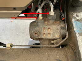
At this point you should be able to see where you'll need to cut this hose to install the other -6 field serviceable high pressure hose end where it attaches to the cylinder assist (part number 16 in the diagram). When doing this, please pay close attention to the red arrows on the diagram and notice where each hose goes on the steering box and where it goes to on the cylinder assist. Do not mix these up, it's important that they are installed correctly!

The easiest way to remember this is that the port closest to the driver on the steering box (part number 13 in the diagram) goes to the port closest to the driver on the cylinder assist (part number 16 in the diagram).

Once you've completed one hose, go ahead and do the same exact procedure for the other.
:)
 
Last edited by a moderator:
Step 16
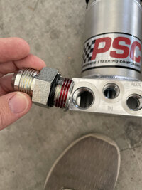
Now you'll want to install the adapter fittings into the fluid reservoir as shown. These are parts 5, 6, and 7 from the diagram and include the -12 outlet adapter, -8 return adapter, and auxiliary port plug. All of these adapters get red loctite on the ends that go into the reservoir.

Apply the red loctite as shown:

IMG_9493.jpg

Now thread the adapter in all the way, then tighten it down with a ratchet and socket until it's tight and flush with the housing as shown:

IMG_9495.jpg

IMG_9494.jpg
:)
 
Last edited by a moderator:
  • Like
Reactions: Lax22
Step 17
Reservoir placement is the most likely cause of many power steering woes. The pump works remarkably well at pushing fluid out but not so great at pulling it in. Since the pump is fed by the reservoir only through gravity, reservoir placement is critical. Things like vehicle position and attitude while driving must be considered when mounting the reservoir. Generally, the higher the reservoir the greater the chance of having a trouble free system. But, there is more to it than just the height. For example, a reservoir mounted high on the firewall will work fine most of the time, but when making a steep climb the pump is likely to starve. Also, the feed line between reservoir and pump should be as short as possible. The greater the distance between the pump and reservoir, the more work the pump has to do bringing the fluid in and the greater the effect of vehicle attitude on the system.

Air in the fluid can wreak havoc on a power steering system. Since the air can compress, whereas the steering fluid does not, much of the force from the pump can be absorbed by the air instead of being properly transferred to the steering box or cylinder. In addition, air can lead to pump destruction. Air causes cavitation in the pump which will greatly increase wear and dramatically shorten the life and performance of the pump.

Reservoir Installation Checklist
  1. Keeping in mind the pump is gravity fed, the reservoir should be the highest point in the power steering system. This will help ensure the pump gets all the fluid it needs as easily as possible, greatly extending the life and performance of the pump. If the reservoir is too low some components may drain back into the reservoir upon engine is shut off. This can cause leaking or, worse, allow air into the system. Another problem with a reservoir mounted low is that the pump will be working overtime, all the time.
  2. It is preferable to mount the reservoir directly over the pump. If this is not possible, in front of the pump is typically better than behind it.
  3. If the reservoir must mount to the frame, body, etc (anywhere not directly tied to the engine) take special care that the feed line will not become stressed during engine torque over or other twisting and flexing maneuvers. 4. Use a baffled reservoir. A properly baffled reservoir will help keep air out of the system. A non-baffled, or poorly baffled reservoir can introduce air simply by allowing air to mix with the fluid as it enters the reservoir.
  4. The feed line should be kept as short and straight as possible. It should not have any dips or sharp bends and should never run below the level of the pump. The feed line should never be crimped, looped, or run horizontal – it should always be flowing downhill into the pump, the steeper the better. The longer the feed line, the harder it is for the pump to draw fluid in. It should not exceed 16 inches. The feed line should also be of sufficient size to meet the demands of the pump, #10 is the recommended minimum. Do not use the supplied -6 pressure line as the feed line, use the -10 feed line. When attaching the feed line to the pump, do not over tighten! The wrench used is typically long providing a great deal of leverage, it is not uncommon to see these fittings twisted off.
  5. The reservoir should be vented, and this vent must remain open. The reservoir cap can be drilled and tapped to accept a 90 degree fitting if this helps with clearance issues. If the vent is spitting fluid, it is a sure sign that air is in the system and needs to be bled.
  6. Do not bend any fittings. Example: bending a 90 into a 120. This will result in restricted flow.
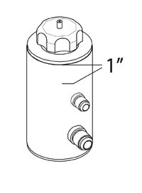
  7. The reservoir should be filled to 1” below the top of the reservoir (see illustration). On single ended cylinder applications this should be measured with the cylinder collapsed.
An example of the proper way to mount a reservoir:

Screen Shot 2021-02-09 at 1.07.53 PM.jpg

The following are examples of what NOT to do:

In this example the feed line is quite short which is a big plus. But, the fact that it is running horizontally negates any benefit.

1.jpg

This image shows multiple violations. It is obvious that the feed line is entirely too long. The slope of the feed line is not great enough. It appears to run flat in some places and even runs uphill in others.

2.jpg

Here the feed line is kinked, cutting off flow to the pump.

3.jpg

This picture shows another hose that has collapsed from using a bend that is too tight. It also shows a big dip in the hose which will cause pump starvation. It also has a drilled tight 90 degree fitting which should be avoided.

4.jpg

Here the feed line starts out just above the center line of the pump and must go uphill to meet the inlet of the pump.

5.jpg

In addition to a loop, this picture illustrates a bend that is too tight resulting in a collapsed hose.

7.jpg

Fill level should be 1” below the top of the reservoir. On single ended cylinder applications this should be measured with the cylinder collapsed. Your reservoir may differ from that pictured here.

6.jpg

Below is how I've mounted my reservoir. Keep in mind that your reservoir mounting may be slightly different based on a variety of factors. I have the GenRight inner fenders which made mounting the reservoir slightly more challenging than it would if I had factory inner fenders.

08759E7B-5DF5-4824-B598-257EA8AA0DF4.jpeg
 
  • Like
Reactions: Lax22
Step 18
You've got your reservoir mounted, so the next step will be to attach your return line from the cooler to the reservoir, and the feed line from the reservoir to the pump.

To do this you'll need to run a hose from the drivers side of the cooler to the return adapter on the reservoir. You'll recall we built one of these lines in Step 10 for the steering gearbox to the cooler. This is the exact same process.

It requires two -8 90° push lock fittings and the -8 low pressure push lock hose. These are part numbers 30 and 31 from the diagram. You'll run the hose from drivers side of the cooler to the reservoir and then cut it to length. Put the Oetiker clamps over the end of the hoses, rub a small amount of power steering fluid on the barbed ends of the push lock fittings, then insert them into the hose. Use the Oetiker clamp tool to fasten the Oetiker clamps, making sure that before clamping them down you have the ends of the fittings clocked in the right direction as to not cause an bind up in the hose.

You'll end up with a hose that looks like this.

IMG_9520.jpg

Tighten this fitting snug onto the adapter on the cooler -8 adapter on the cooler (it only fits on one of them so this should be obvious) and now you'll move on to the -12 feed line from the reservoir to the pump.

To do this you'll need the -12 90° fitting, -12 hose, and -12 45° fitting (parts 8, 9, and 10 from the diagram).

I started by taking the -12 hose and inserting the -12 45° fitting on one end of it before even cutting it. This fitting is quite a bit more tricky to get into the hose than the previous fittings you've installed so far. My best advise is to carefully (making sure not to damage the fitting) put the -12 45° fitting in your vise with the barbed side out. Apply a thin layer of power steering fluid around the barbed side of the fitting, and also to the inside of the hose end you intend to put on the fitting.

Get your gloves on and get your heat gun out and heat the end of the hose until it's very, very hot. For me this took about 2 minutes. Once you're done heating the hose, immediately slide it over the barbed end of the fitting. The heat should make the end of the hose slightly more pliable, but it's still going to take some force to get on, which can be done rotating the hose back-and-forth while you're pushing it down onto the barbs.

Once the fitting is all the way in, you can then attach that end of the hose to the power steering pump, making sure that while doing so the angle of the -12 45° fitting is pointing the hose in the right direction of your reservoir in such a way that it won't cause any forced tension or kinking of the feed line.

You should now be able to determine the length your hose needs to be in order to attach to -12 adapter on the reservoir. Make your mark with a pen as that's where you'll be cutting. Keep in mind that after installing the fitting on the end of the hose it may lose about 1/2" in length due to the hose expanding over the fitting.

Remove the hose from the power steering pump, put the hose in the vise, and use your cutting wheel tool to cut the hose to length. After this is done I would suggest using paper towels and water and cleaning out the inside of the hose as good as possible, since it's likely you have debris inside the hose from cutting it. Getting those debris inside your power steering system will wreak havoc, so they must be cleaned out before installing the feed line.

Once this is all done you can install the final -12 90° fitting, making sure that when installing it it is clocked in such a way that allows the hose to connect to both the power steering pump and the reservoir without being kinked in any way. Tighten the fittings down on both ends and you're done here.
 
Step 19
Now that you're ready to put everything back together and test out your new PSC hydro-assist steering, you'll want to do a few things before you do:
  • Reinstall pitman arm
  • Reinstall drag link on pitman arm
  • Reinstall passenger side headlight
  • Reinstall front bumper
Check torque specs
Go through everything you've been working on and make sure everything is torqued to spec. Namely the track bar bolts, steering box-to-frame bolts, pitman arm, power steering pump, etc.

You can find the factory torque specs in this thread here: Jeep Wrangler TJ Torque Specs (1997-2006)

Aligning vehicle
Before bolting everything back up, you'll want to align your steering by setting the toe-in. If you don't already know how to do that, see this thread: How to align your Jeep Wrangler TJ
:)
 
Last edited by a moderator: