Renewing the 2001 Wrangler—a build saga

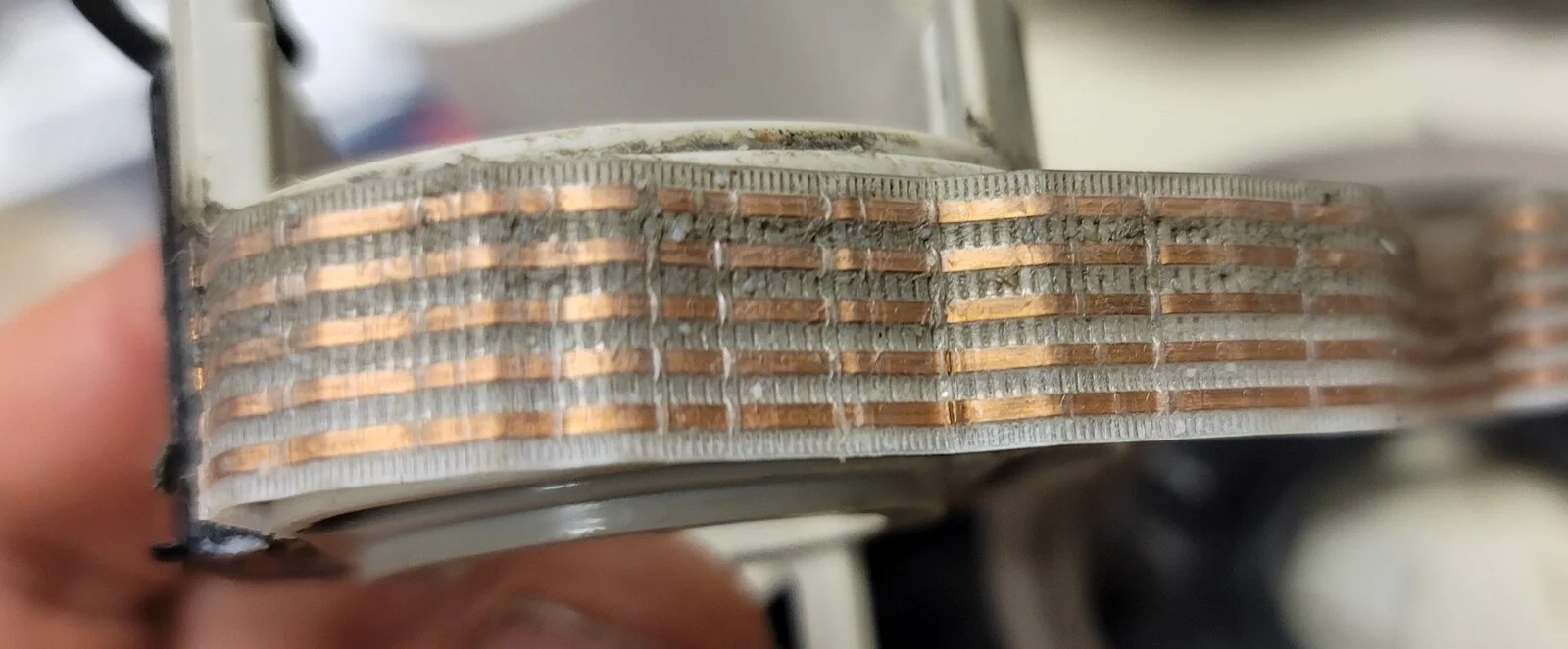
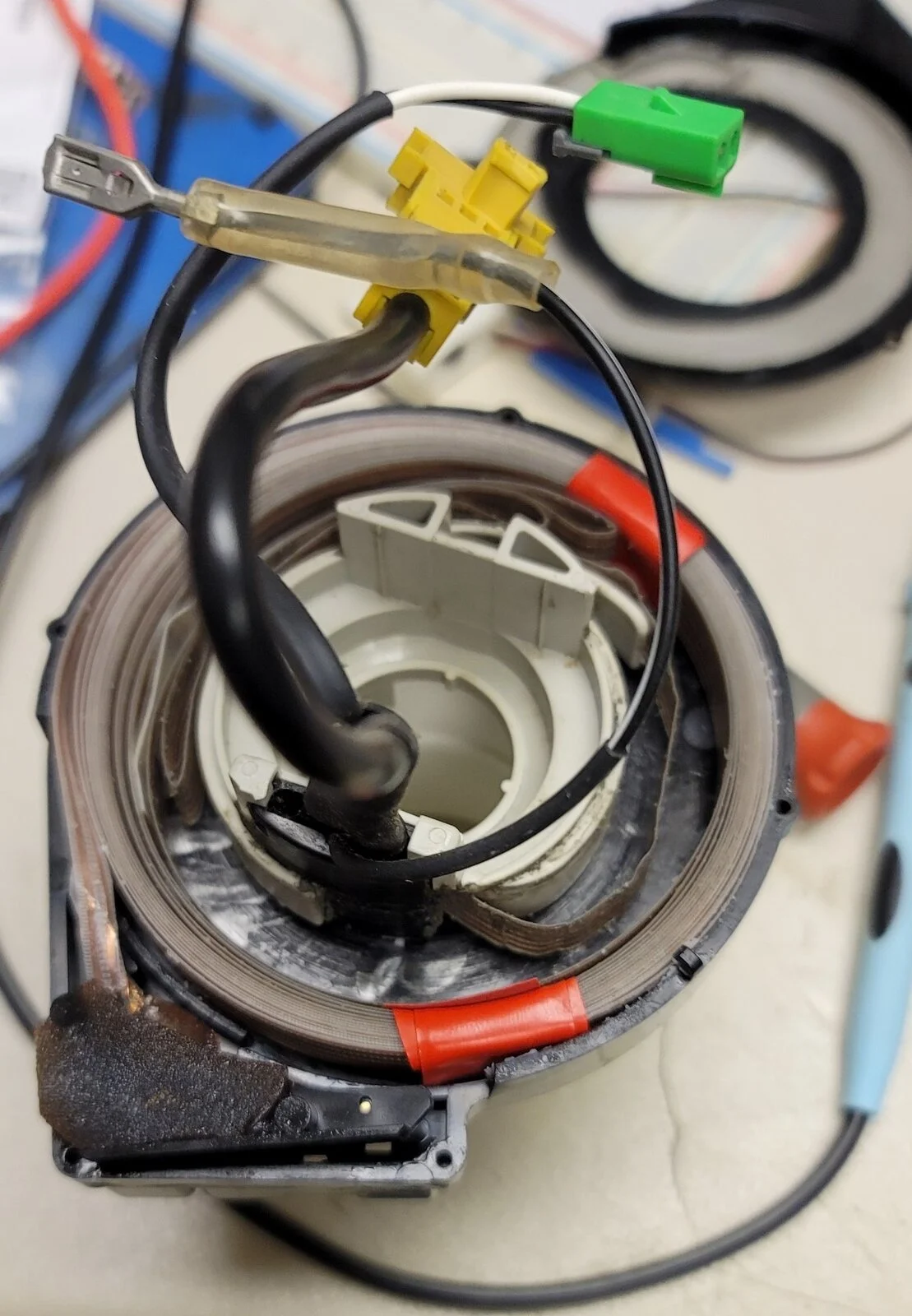
First thing is to keep that whole ribbon cable that makes up the clock spring from unwinding and twisting itself all over the floor. It's already tried to spring out even with the light handling that I've been doing. Taking two pieces of electrical tape and carefully lifting each side of the ribbon cable out, I was able to secure the ribbon cable from unwinding accidentally. I did make sure to leave the outer layer and 2 inner layers out of my tape so that I could make repairs on what I've seen so far:
9.webp


With that secured, I can now safely pull the center hub and the connector piece from the clockspring's housing. Starting with the connector side, I've encountered the first of several "snot-sealants" that will need to be removed. They are super-sticky and I'm suspecting part of the waterproofing/dustproofing for this part. The one think one (about 1/4") on the connector came off pretty much intact and looks like I can reuse it later. The others are too thin and are unlikely to be salvageable.
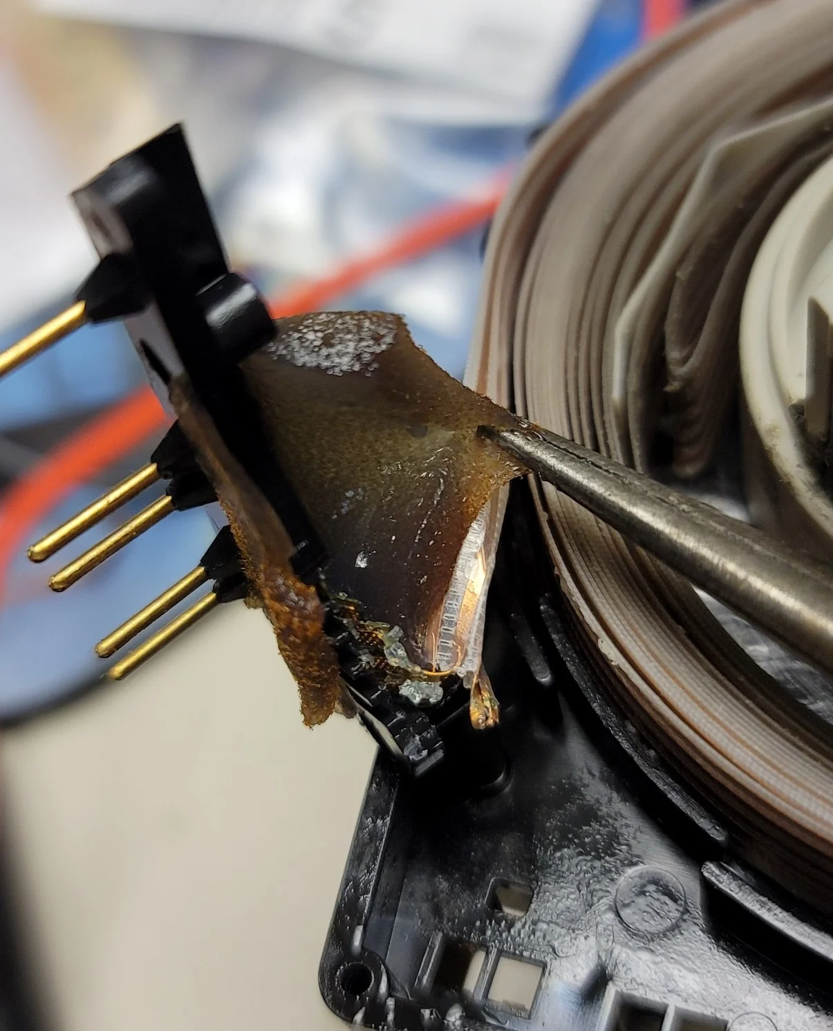
12.webp


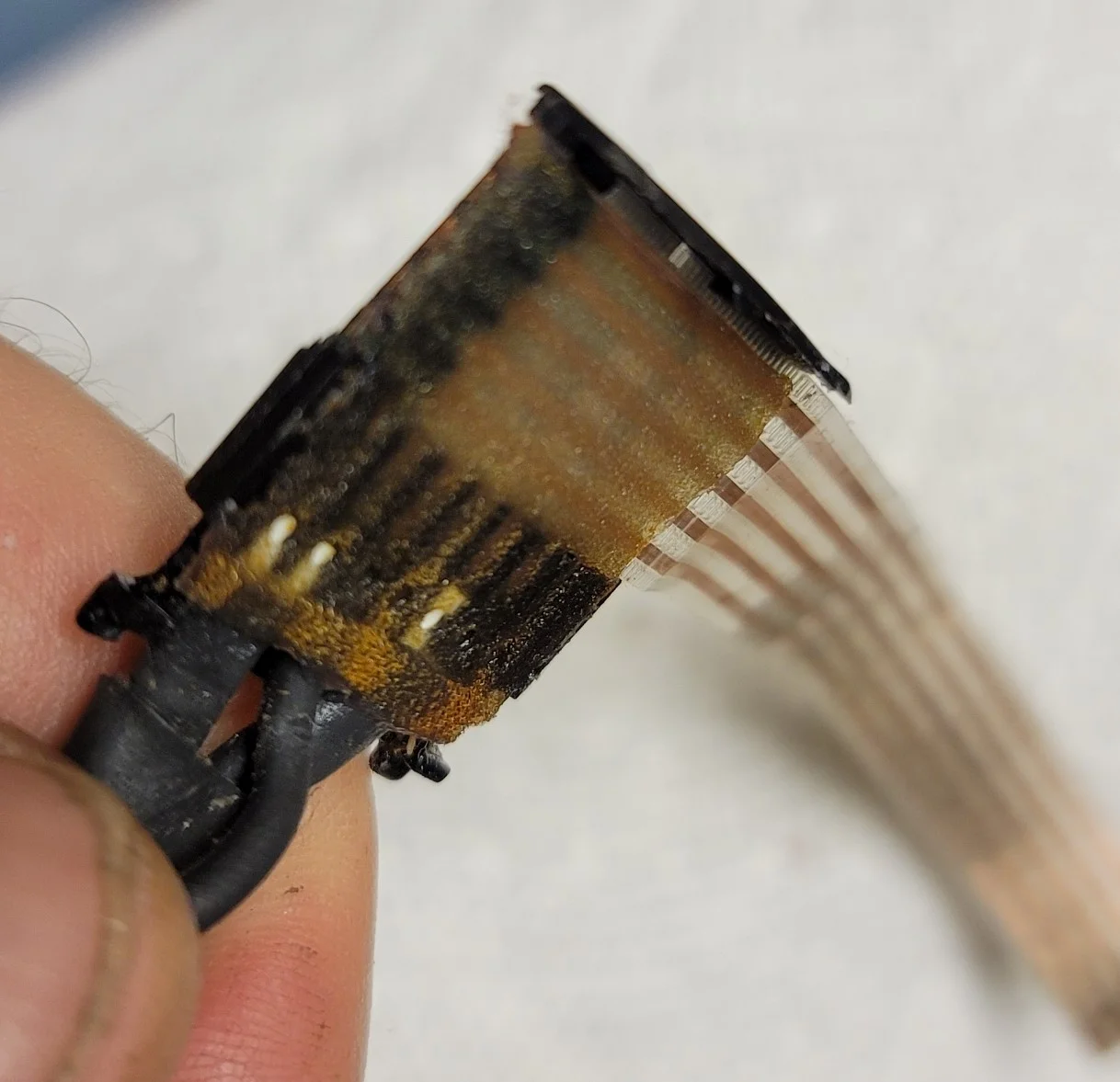
Inspecting the connector end further, the breaks are clear and bad:
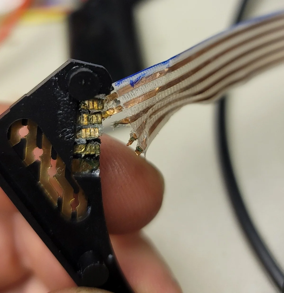
13.webp


The blue ink on the top of the ribbon cable is my own. I marked the top edge of both the connector and center hub ends so that I can keep the orientation straight for my rewiring attempt. Since this connector end is toast, might as well cut it off with some sharp electrical scissors and clean up those contacts for future soldering:
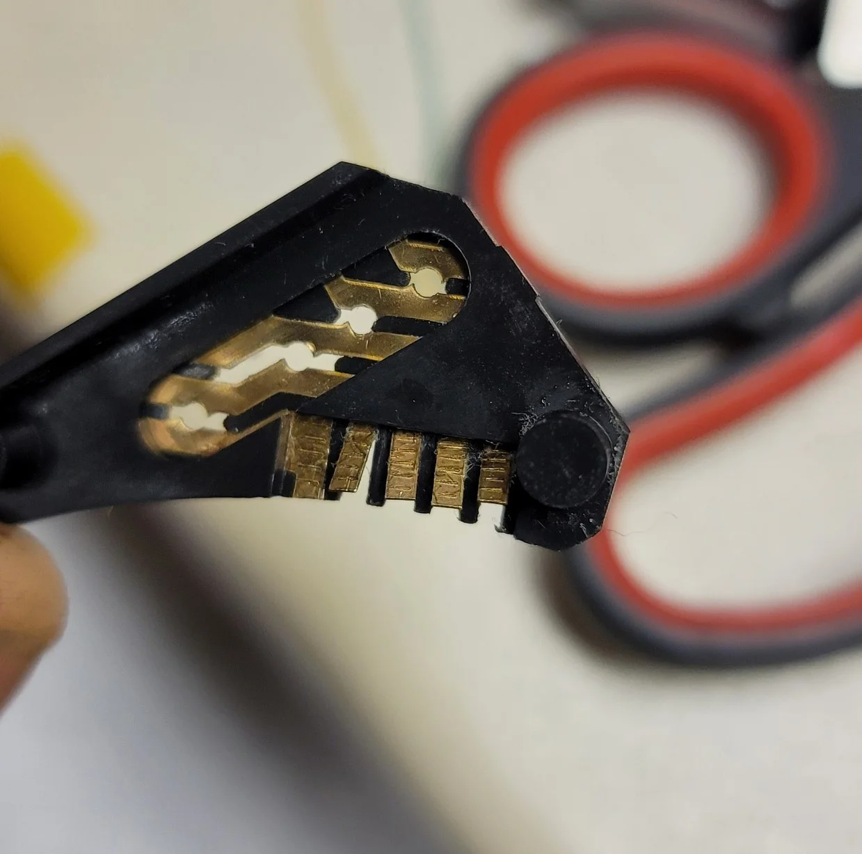
14.webp


Pulling the center hub out, I could also see several more breaks in the ribbon cable's copper:
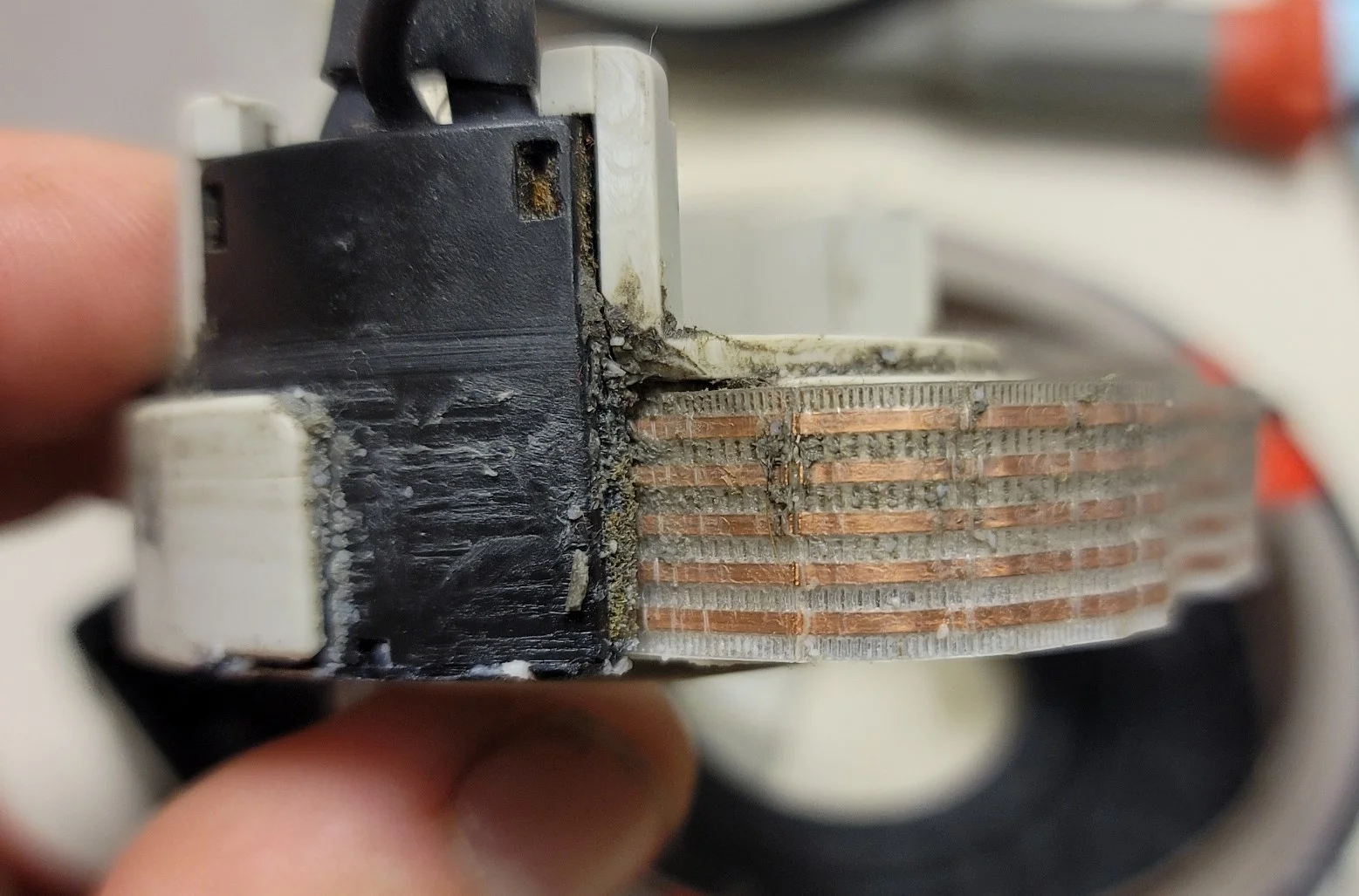
16.webp

17.webp


There's a small black tab on the center hub that holds the black hub cable connector to the light gray center hub itself. Gently prying that out, I could get to the center hub connector too:
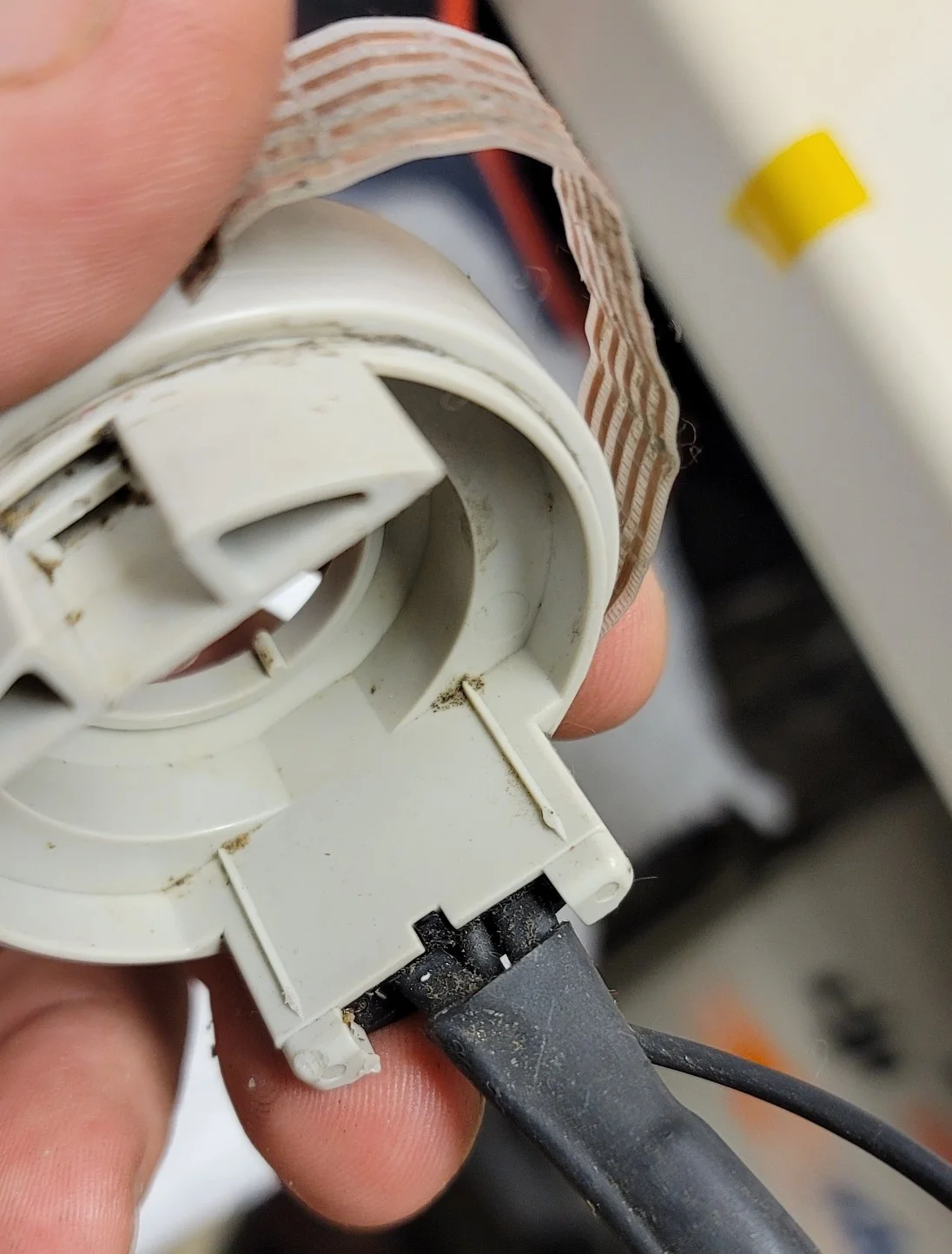
18.webp


Since the hub wiring is so bad as well, I just went ahead and cut it back to where the ribbon cable seemed in good condition. I also straightened and inspected some of those other loopbacks:
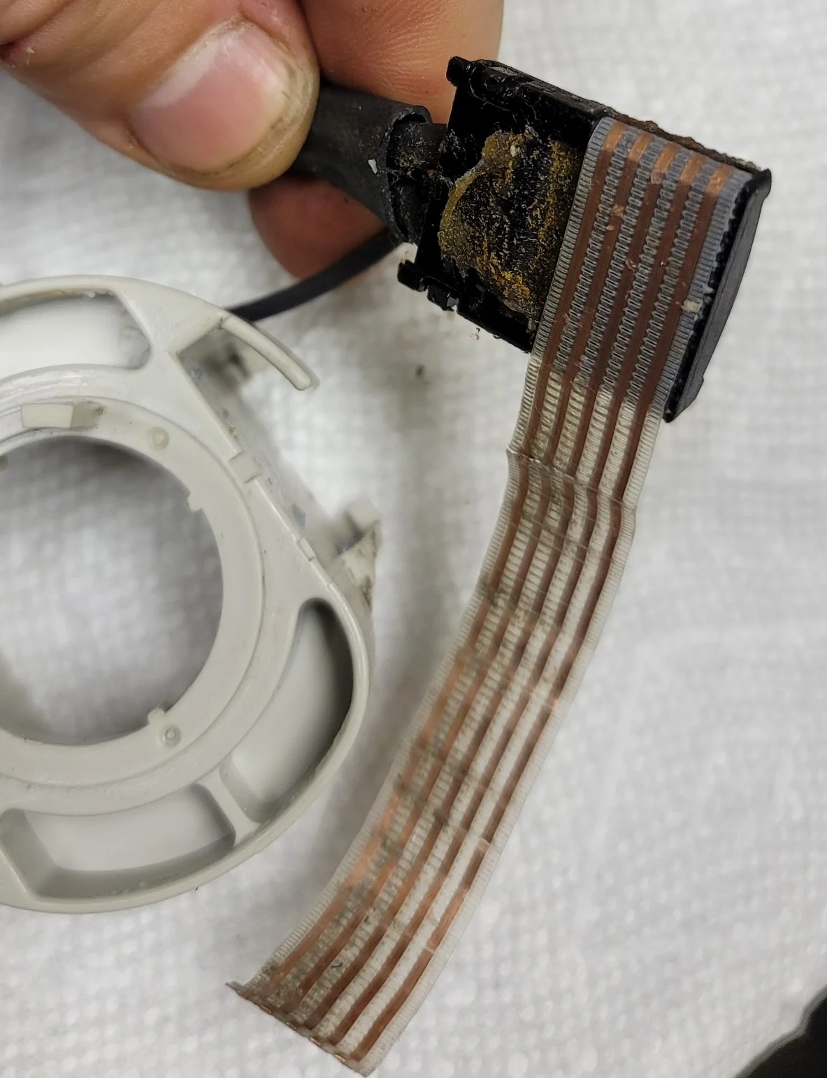
19.webp


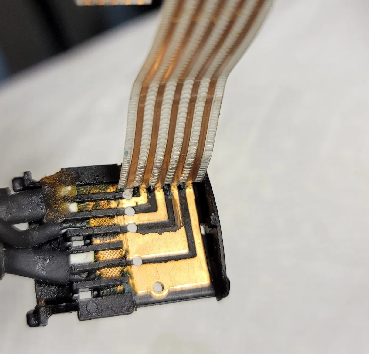
The center hub connector has more snot-sealant to be removed so that we can work our way to the connection point for some attempted resoldering:
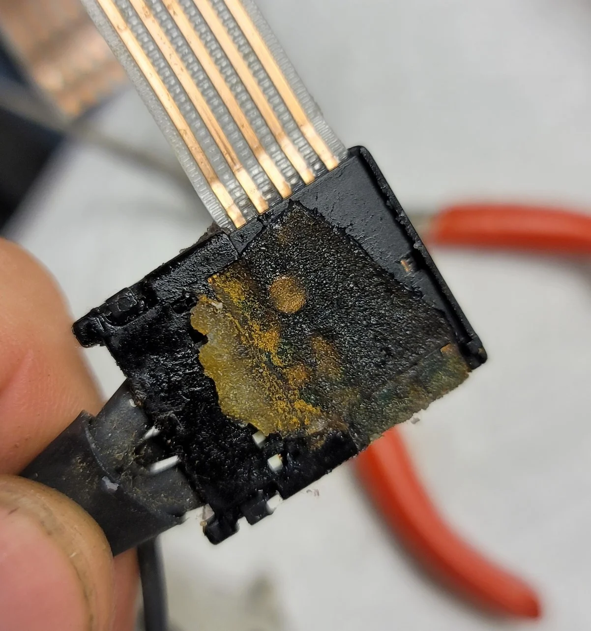
20.webp


This black center hub connector is made up of two parts that clamp the ribbon into place. Gently prying back two black tabs, we can remove the "cover" and that will let us access the rest of the connector...with more snot-sealant in the way of course:
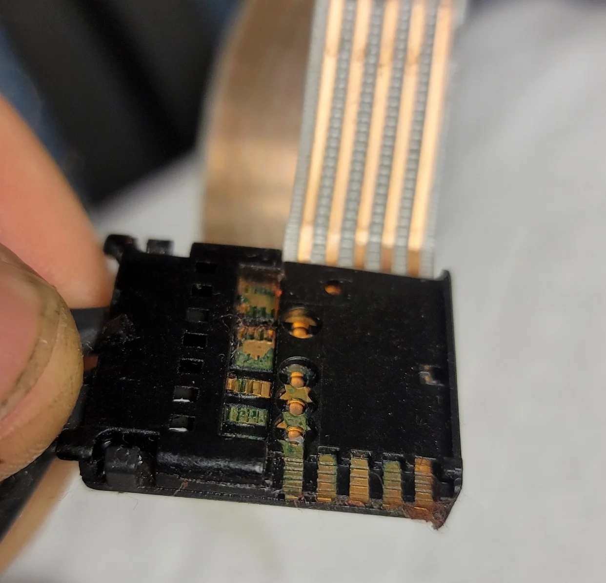
21.webp

22.webp

23.webp


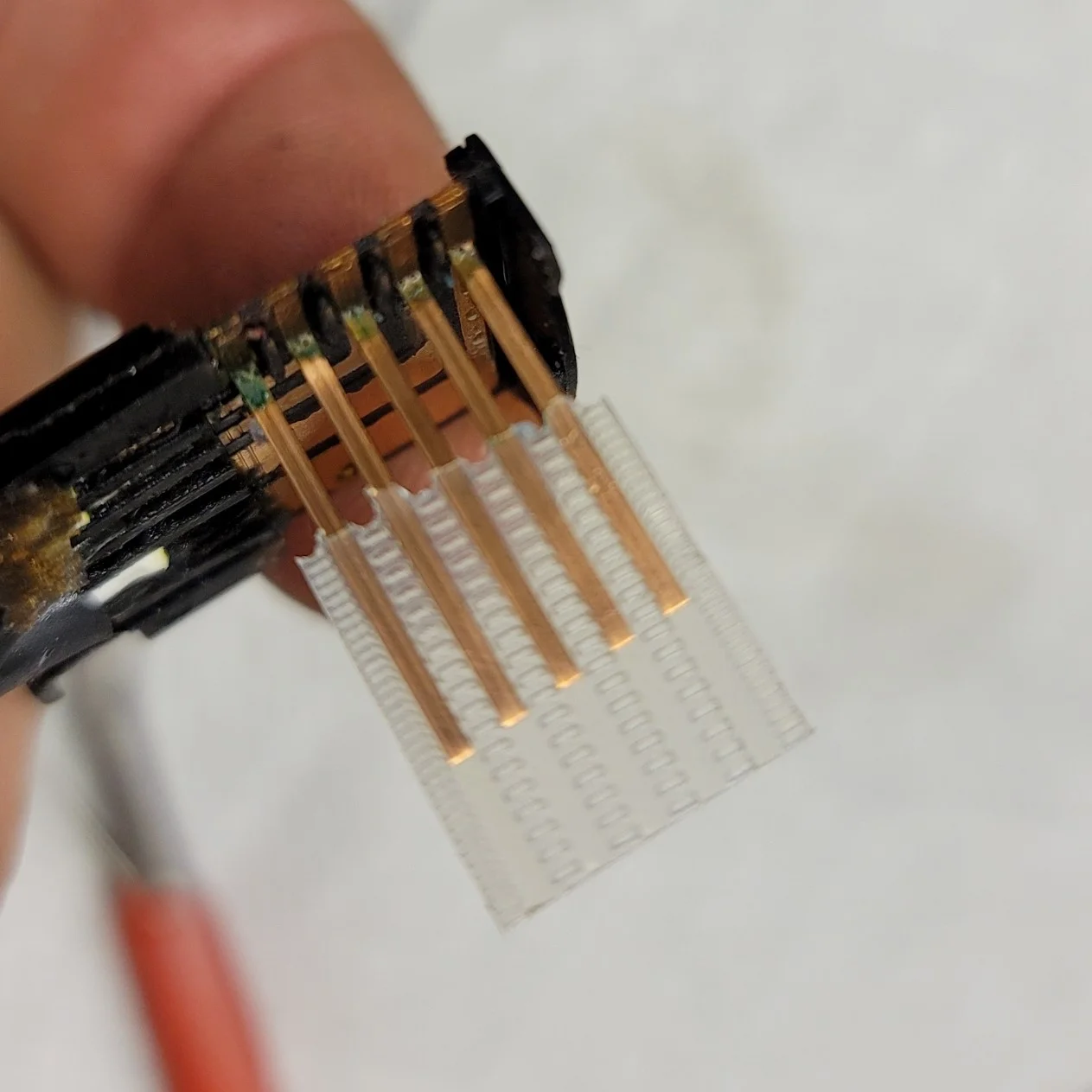
Trimming the ribbon back also yielded one more discovery. If you gently pull on the ribbon cable's clear plastic jacket, you can slide it off of the copper wires. This is a handy technique for exposing the wires for soldering.
24.webp


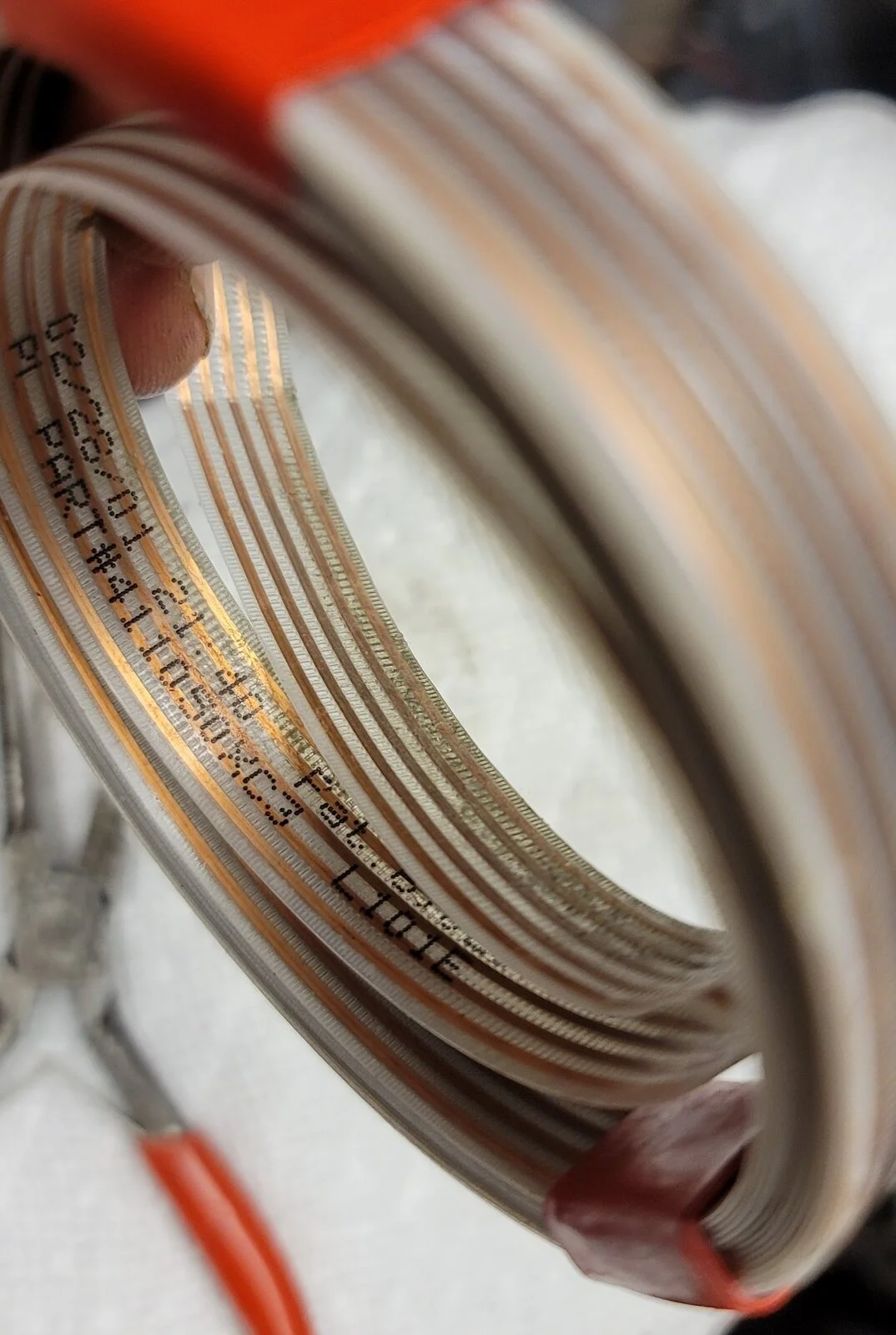
And yet another discovery. This entire interior ribbon cable has a clearly marked part number:
25.webp


I already searched online for it and couldn't find anything. If anyone can locate it, that would be some helpful information for future repairs.

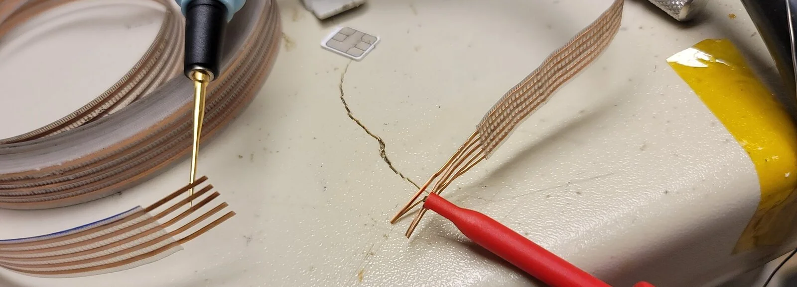
Last steps before we start to reassemble is just to test out the ribbon cable and see if there are any other obvious issues. Continuity testing each segment independently and then cross-checking them all for shorts shows that the rest of the cable (not counting the roughly 12" i cut from the ends) seems to be in good condition. I did wiggle and lightly bend the ribbon cable while testing to try and make a short show up if one existed down in that spool, but it all seems to be in working order.
27.webp


Next post will be the reassembly process!
 
After cleaning each of the connectors' pads, my plan is to lightly tin each connector with solder, lightly tin each ribbon cable end with solder, and then quickly solder join each of them together.

Starting with the center hub connector first, I put a very small tip on my solder iron and set the temp to 350C. Trying to avoid contact with the plastic of the connector, each tab tinned up OK after a few seconds. The connector's plastic is not super heat sensitive but it did soften a little just as the solder was flowing:
28.webp


Attaching the ribbon cable...and paying attention to the top orientation that I marked earlier:
29.webp


I don't really want to reuse the snot-sealant gunk that I removed earlier...except for the thick piece that came off OK. I chose to treat these exposed areas with some modern liquid-tape (https://www.gardnerbender.com/en/p/LTB-400/Liquid-Electrical-Tape-Werpro-Seal) instead:
30.webp


Wrapping this center hub section of the ribbon cable back around the edge, we can prep the black cover for re-installation:
31.webp


As I was installing the center hub's black cover, I did notice a small break in the light grey plastic in the right corner. More on that to come in a minute, but that's the location for that random light gray part from the earlier pictures.
33.webp


Moving on the connector plug at the other end of the cable, the process is same as above. First, tin the ends:
34.webp


Solder on the ribbon cable wires paying attention to the orientation from the earlier marks:
35.webp


More liquid tape to protect the connections on both sides:
36.webp

37.webp


And we're now ready for reassembly. But before we do that in the next post, a quick retest for continuity on each connector and to check for any cross-wire shorts. Good news is that there were no problems! I did also draw up a quick pin-out chart which looks like this:
50.webp


I think that's self-explanatory, but feel free to ask questions if not. Now...on to reassembly!
 
For the pin connector end to fit back into the clockspring housing, it needs to have a 90 degree bend carefully made. This allows it to rest in the connector location and for the ribbon cable to thread through an outer channel in the clockspring housing. First, carefully make the bend and avoid pinching the wires:

38.webp


Then place the ribbon cable back into the housing and the outer channel. I also re-installed the 1/4" snot-sealant on the pin connector as well:
39.webp


I still hadn't quite figured out how to re-glue the loose light gray piece on the center hub yet...so you won't see it correctly in some of the pictures below, but this is the best time to go ahead and repair that part so I'm including it in the description now. You can see where it attaches and where it broke from here:
47.webp


And with a little bit of medium CA glue along with about 5 minutes of careful holding, it's now firmly back in place. I did also put a small bit of CA glue down the back of the light gray piece where it touches the black center hub connector. It really seems to need this extra reinforcement as the OEM connection is just that very tiny plastic corner that's going to get stressed every time the ribbon cable flexes. Not the greatest of designs. With my additional gluing, that will likely make future repairs tougher since these are now glued, but I went light on the glue and it's in a spot where a quick run through with an exacto knife blade should free it easily. Here's the completed, repaired center hub:
48.webp


With everything in place, we can now remove the safety binding that I put on to keep the ribbon cable from becoming unsprung. I just used my exacto knife with the blade up to carefully cut through the red tape. The tape then pulls free very easily:
40.webp


I wanted to test the movement and make sure that I got the center hub as close the the middle of the rotation cycle as I could. That way, I'd have the maximum amount of both left and right turning available. To do that, I wound the clockspring up clockwise until it was just beginning to bind while I had the center connector at the bottom/180 degree point. The pressure on the cable was very acceptable and mine looked like this at that point:
41.webp


I then unwound it counterclockwise until it reached a comfortable unspooled limit. I again stopped with the center connector at the bottom position. In total, that was FOUR revolutions. That means that if I return it to the center position, I should have two easy revolutions in either direction before any binding occurs. That's more than enough for my TJ's steering setup. Here's what it looked like in the unspooled position:
48.webp


After winding it back up two revolutions to the middle position, it was ready to put back together. But before I can do that, I need to deal with those two "gaskets" that were on the top portion of the clockspring. Both were in pretty bad shape and I wanted to get them back to flat:
43.webp


My solution was to try a bit of flat heat and pressure. I took a piece of parchment paper, placed it on a flat wooden block, heated up a normal iron to medium temp, and place each ring in between two layers of parchment paper:
44.webp


After about 5 seconds of heat and pressure, I pulled them out and they look MUCH better! Nice and flat. Still has some of the edge damage on them but they really do look very usable:
45.webp


Installed back on the top section of the clockspring, they are now sitting nicely:
46.webp


Carefully mating the top and bottom halfs together, looking for any missed alignment, and then reconnecting with the five torx screws, the clockspring now looks ready to go!
49.webp


I did doublecheck all pins and connectors for continuity and for any cross circuit shorts. Repeated this with the hub rotated at -2, -1, 0, +1, +2 revolutions from centered and all came out great! Pulled my battery cables, steering column cover, steering airbag, and steering wheel and I was able to swap out the clockspring in about 15 minutes. A quick reassembly and all seems to be back in working order: horn works and airbag warning light is now off! A short test drive and all seems to be holding steady. So, 2 hours of time and some careful work and I do think that this one is OK and safe to use. At some point I'll pull apart my prior clockspring to see what issues it has and will likely repair it and keep for a backup.
 
My dome light cover...somewhere in the last 10 years it has gone missing. Been looking for a replacement for this part too but haven't been able to find one just yet. So...time to make one.

Removed the dome light housing from my 2001 TJ's soundbar so that I could make some precise measurements from it. Fired up Fusion360 and drew up an outline rim so that I could test the fitment and see if I could make a 3D printed version that would attach as snugly as the OEM one that was hard plastic.

Well, I couldn't get anything that I felt was really secure and that would stay attached with both bumps and temperature changes. And I guess even the OEM one was prone to failure seeing how it came lose and got lost somehow. So I decided to just use the housing's mounting bolt locations to create a cover that would bolt both itself and the housing to the soundbar. I went through a few test versions with some diffusion grating (not needed in the end), some bolt support posts (not needed!), and some different thicknesses for the transparent PETG material that I planned to print from in the end.
1.jpg


The final model fits the dome light housing nicely:
2.jpg


And the transparent PETG works well with the LED light in my TJ:
4.jpg


And it beats having a "hole" in my soundbar:
5.jpg


If anyone is interested in trying one as well, here's the render and STL:
10.png


STL file for the print is attached
 

Attachments

That's some great, and patient, work. Nicely done, and thanks for the detailed posts.
 
Updated the dome light cover design slightly. A little less boxy by reducing the vertical dimension and then rounding the edges a bit. Only reason I didn't round it to start with is that I wanted the viewable portion of the light to be printed directly on the print bed so that it would be smooth. To round it and not have bad print artifacts (stringiness), I then needed to flip it on the print bed. It created much more support material to clean off the print, but turned out with a much better profile.

EDIT: I got it to upload the pics and the STL file correctly for the new design. Leaving this one in place for now.
6s.webp
7.webp
 

Attachments

Last edited:
On to today's TJ issue: HEADLIGHTS. More specifically, my headlights will only operate on high beams. The high beam light is on and both lights are definitely on high beam. Operating the multi-function switch has no effect...if the lights are on at all, they were both on high and the high beam indicator was illuminated.

First thing I checked was the fuse. Since the lights are working on high and there's only one fuse, didn't expect anything other than a normal fuse...which is exactly what I found.

Second thing to check was the multi-function switch. There are lots of good references on removing, diagnosing, and repairing that part online so nothing new to add there. Visual inspection of the multifunction switch showed no issues. A quick continuity check with the correct pins also showed nothing out of order.

Third thing was to check again to see if there was a relay or something that could be bad. Nope. The 2001 TJ is essentially a straight circuit through the multifunction switch to the low and high beams.

Fourth thing I checked were the headlight connectors themselves. This is where I found my issue. On the passenger's headlight connector, the wire insulators were really pulled back from the connector and were clearly touching each other. Low and high beams shorted together. Essentially, voltage was being passed down both the high and low beam connectors at all times. Given the image below, it's amazing to me that they hadn't shorted out to the negative cable yet.
HL1.jpg


Wiring colors for these connectors are:
- RED/ORG = 12V High beam
- VLT/WHT = 12V Low beam
- BLK = ground

Dropped by my local Orielly's and picked up some new connectors (https://www.oreillyauto.com/detail/...001-jeep-wrangler?q=headlight+connector&pos=2) and decided to throw a DT connector between the two:
HL2.jpg


HL3.jpg


Same on the TJ's wiring harness and then reattached the new connector to the headlight. Low beams and high beams are now both available again!
 
Last edited:
  • Like
Reactions: SoCalGlide
So I've been having the airbag warning indicator make a tone and come on. It would happen randomly (I started timing it after startup to see if it was on some type of delay) and I feared that my clockspring repair had not worked out as well as I hoped.

Pulled the clockspring again and cycled it carefully while doing some resistance testing to see if something was wrong. It tested out just fine. Replaced that and decided to monitor again for another week.

Same issues happening again with the airbag indicator. By chance I happened to look down by the shifter and saw that the passenger airbag light was also on...even though my passenger airbag switch was keyed to "enabled". Started watching that more closely and I noticed that the passenger airbag warning light would come on a few random minutes after the main airbag light was warning on the dash.

Decided to pull the passenger airbag warning switch and give it a look. I didn't take pictures but I was able to remove that "housing" without removing the entire center console. Per some other writeups on the forum, I reached under the center console and was able to barely release one of the tabs on the front, right corner. After that I carefully pulled it until the front, left corner tab released. Probably saved me 30 minutes versus pulling the whole center console.

Two quick screws removed and the switch/light mechanism is free. sliding out the small circuit board and plastic backing, I could get to the warning bulb itself. I had to throw on my magnifiers but sure enough the filament in that tiny bulb was broken on one side...broken in such a way that I suspect it was randomly making contact as I drove.

Again, reading on this forum, that lamp circuit being broken triggers the overall airbag warning to activate. Time to replace it!

I ordered the bulbs that I'd seen recommended by others: "CEC Industries 7219 Wire Terminal". Two quick desolders, inserting the new (non-polarized) bulb into place, and two quick resolders and it was good to go. One note: those replacement bulbs were smaller than my OEM bulb but so far seem perfect. Again, sorry that I didn't snap any pics this time. If someone needs some, just reply and I'll pull things and document the process further.

Reinstalled everything and went for a few drives this weekend. So far, everything is working 100% correctly. Hopefully, another TJ gremlin has now been defeated.
 
  • Like
Reactions: NashvilleTJ
I've been having a bit of play in the steering wheel. Not too bad, but about 1.5" to 2" inches of radial slack in the steering wheel before the steering box engages and the linkages respond. After going through all of the inspections of ball joints, linkages, etc. (most of which was new only 18 months ago when I replaced my original axles and steering linkages) I decided that it must be some play in the old u-joints in the steering shaft. My steering shaft was the original part from 2001 so wanted to replace it.

Decided on the Borgeson upper and lower shafts for the rebuild. One thing to note if you're installing these Borgeson parts: if you want either of them to slide along their shaft extension, there is a set screw hiding underneath the flex boot on both shafts. The boots themselves came with a zip tie on the flex boot that needed removal in order to slide the boot and expose the set screws.
20220908_095025.webp


I left the set screws loose for the installation AND left them loose for the first few steering tests to let the shafts and joints slide into a comfortable length that avoided binding and operated smoothly. Once all was good, I re-tightened them firmly and moved the boots back into place.

I put the lower shaft on first. One difference to note from the OEM shaft, the new bolt at the steering box didn't just clamp the shaft end on the splines, it also lines up such that the bolt rests within a recessed cutout on the splined shaft. My OEM lower shaft was clamp only and the bolt didn't engage the steering box's shaft.
20220908_103605.webp


I did pull out, clean, and re-grease with some lithium grease the roller bearings and plastic retainers on the lower shaft's support that attaches to the frame. I didn't get any pictures of that support unit while I had it pulled out but mine wasn't too bad. Only some minor surface rust that cleaned right up. Here it all is reinstalled;
20220908_103521.webp


The upper shaft mates to the end of the steering wheel column in a similar fashion as the lower shaft mated to the steering box: it has a clamping bolt clamps onto the steering column AND has a set bolt that secures into a cutout on the steering wheel column itself.
20220908_103706.webp


Last part was attaching the debris seal for the upper shaft against the interior firewall. Four small self-tapping metal screws hold it in place.
20220908_103654.webp


After some stop-to-stop tests in the garage and then re-tightening the shafts' length adjustment set screws, I took it on the test drive. A few quick observations:
1) my steering play is nearly 100% eliminated! There may be 0.5" of play left if any.
2) the new shaft had a tiny bit of "binding" when making tight turns to the right on the road. It didn't prevent moving the wheel, but I could feel the u-joint stiffening up slightly at one point. I ended up loosening those length-adjusting set screws and driving very carefully/slowly with the shafts loose so that the joints could "push" the lengths to a happy place. It worked and and re-tightened it all. The binding disappeared.
3) the new setup feels firmer. Not stiff but rather more consistent resistance. Almost like it's "heavier" to turn but very smooth. Not sure if that's having the support bracket cleaned and freshly lubricated or the shaft replacement itself. Either way, it feels more solid.

Pleased with the swap so far. Will update in a few weeks with any changes.
 
For the pin connector end to fit back into the clockspring housing, it needs to have a 90 degree bend carefully made. This allows it to rest in the connector location and for the ribbon cable to thread through an outer channel in the clockspring housing. First, carefully make the bend and avoid pinching the wires:

View attachment 272467

Then place the ribbon cable back into the housing and the outer channel. I also re-installed the 1/4" snot-sealant on the pin connector as well:
View attachment 272468

I still hadn't quite figured out how to re-glue the loose light gray piece on the center hub yet...so you won't see it correctly in some of the pictures below, but this is the best time to go ahead and repair that part so I'm including it in the description now. You can see where it attaches and where it broke from here:
View attachment 272469

And with a little bit of medium CA glue along with about 5 minutes of careful holding, it's now firmly back in place. I did also put a small bit of CA glue down the back of the light gray piece where it touches the black center hub connector. It really seems to need this extra reinforcement as the OEM connection is just that very tiny plastic corner that's going to get stressed every time the ribbon cable flexes. Not the greatest of designs. With my additional gluing, that will likely make future repairs tougher since these are now glued, but I went light on the glue and it's in a spot where a quick run through with an exacto knife blade should free it easily. Here's the completed, repaired center hub:
View attachment 272470

With everything in place, we can now remove the safety binding that I put on to keep the ribbon cable from becoming unsprung. I just used my exacto knife with the blade up to carefully cut through the red tape. The tape then pulls free very easily:
View attachment 272471

I wanted to test the movement and make sure that I got the center hub as close the the middle of the rotation cycle as I could. That way, I'd have the maximum amount of both left and right turning available. To do that, I wound the clockspring up clockwise until it was just beginning to bind while I had the center connector at the bottom/180 degree point. The pressure on the cable was very acceptable and mine looked like this at that point:
View attachment 272474

I then unwound it counterclockwise until it reached a comfortable unspooled limit. I again stopped with the center connector at the bottom position. In total, that was FOUR revolutions. That means that if I return it to the center position, I should have two easy revolutions in either direction before any binding occurs. That's more than enough for my TJ's steering setup. Here's what it looked like in the unspooled position:
View attachment 272475

After winding it back up two revolutions to the middle position, it was ready to put back together. But before I can do that, I need to deal with those two "gaskets" that were on the top portion of the clockspring. Both were in pretty bad shape and I wanted to get them back to flat:
View attachment 272476

My solution was to try a bit of flat heat and pressure. I took a piece of parchment paper, placed it on a flat wooden block, heated up a normal iron to medium temp, and place each ring in between two layers of parchment paper:
View attachment 272477

After about 5 seconds of heat and pressure, I pulled them out and they look MUCH better! Nice and flat. Still has some of the edge damage on them but they really do look very usable:
View attachment 272478

Installed back on the top section of the clockspring, they are now sitting nicely:
View attachment 272479

Carefully mating the top and bottom halfs together, looking for any missed alignment, and then reconnecting with the five torx screws, the clockspring now looks ready to go!
View attachment 272481

I did doublecheck all pins and connectors for continuity and for any cross circuit shorts. Repeated this with the hub rotated at -2, -1, 0, +1, +2 revolutions from centered and all came out great! Pulled my battery cables, steering column cover, steering airbag, and steering wheel and I was able to swap out the clockspring in about 15 minutes. A quick reassembly and all seems to be back in working order: horn works and airbag warning light is now off! A short test drive and all seems to be holding steady. So, 2 hours of time and some careful work and I do think that this one is OK and safe to use. At some point I'll pull apart my prior clockspring to see what issues it has and will likely repair it and keep for a backup.

Thank you, did it sucessfully on a 05 tj.