Introducing Big Juicy

There was a batch of fuses from Harbor Freight that would not blow. They melted lots of wires. Try a known good 10A from a good supplier and see if that fixes the problem.

While it is 100% possible that the existing fuse was a HF special that wouldn't blow, what I can now say is that if you replace the fuse with an AutoZone 10A it will blow immediately.

So why didn't the existing fuse blow? Because the PO used a 30A fuse.....probably because he kept blowing 10A fuses while his TCC wiring was jacked up. Then at some point it broke to the point where it was no longer an issue. Then I came along and mis-fixed it and re-introduced the problem. That's my best guess anyway.

I checked the fuse at some point along the way but didn't realize it was the wrong size until I actually typed out the size in my post earlier today, and then went out and looked. I guess you can take nothing for granted if it hasn't been in your possession since it rolled off the assembly line.
 
unplugged the TCC, no blown fuse no smoke. Plugged TCC back in upside down, no blown fuse no smoke. Also can hear the fuel pump kick on, so something with the TCC is definitely causing a lot of strife, but it seems that I can at least work around it for the time being. Can't test the gauges or OBDII with the dash out, but I'm willing to bet I have fixed that as well.

I need to really analyze the TCC circuit, because I'm not convinced it should matter how it's wired. Or rather, I don't (yet) understand why it matters how it's wired, and I'm not (yet) convinced I did it wrong despite the symptoms. At their core, solenoids aren't directional, so something else is making the polarity important. I have a new solenoid on hand, and there are two leads coming off it and they're both identical so it's only 50/50 you would wire it in the right way, meaning you would only have a 50/50 of plugging the external plug in correctly. That can't be how this works. But on the other hand it's the only connector I'm aware of that will fit in multiple orientations, so maybe???

TCC circuit analysis

Here is what the path looks like from the factory:

fuse #11 ==> 20ga RD/LG wire ==> TCC solenoid ==> 18ga OR/LG wire ==> PCM cavity B11

The RD/LG wire is the "Fused Ignition Switch Output (Run/Start) which means that the Red/Light Green wire has 12V on it when the key is ON. When the PCM decides to lock up the torque converter, it does so by providing a ground on the OR/LG wire. So the nominal state is that the OR/LG wire is not grounded? That makes sense: the circuit is essentially always open/incomplete until the PCM provides ground, which is why unplugged doesn't make the thing lock up & stall/prevent starting.

Of course I found my OR/LG wire cut near the PCM plug with a new black wire spliced in at the connector, so what I should actually have is:

fuse #11 ==> RD/LG wire ==> TCC plug cavity A
==> {the actual solenoid} ==>
TCC Plug cavity B==> OR/LG wire ==> new black wire ==> stub of OR/LG ==> PCM


And because I had to splice in a new TCC plug I needed to add in some new wire. I took a pic of this and have verified these splices. Although maybe there is more to this story since the pictured red splice is clearly not an 18ga wire...it might be a relic of my temporary fix in this area over the summer; that could be a red 14ga, which would mean there is one more splice further up in that insulation. I seriously doubt I would've done all this work and left an unnecessary splice but maybe I thought I needed the length? I'll have to verify that this afternoon. I guess I can also test for voltage with the key on, that will tell me how I have it wired upstream. I need to make a new year's resolution to use my voltmeter more.
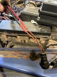
image0.jpeg

At any rate this is how I believe it is currently wired:

fuse #11 ==> RD/LG wire ==> Red splice ==> RD/LG wire ==> TCC plug cavity A
==> {the actual solenoid} ==>
TCC plug cavity B ==> OR/LG wire ==> new black wire ==> stub of OR/LG ==> PCM

As far as I can tell, I have this wired up correctly. So we're back to this basic symptom: if I plug the TCC in one way, it blows the fuse and I get no fuel pump (among other things). If I plug it in the other way everything seems to work & the jeep will start. Maybe I should flip it back and make sure the fuse blows again, and do my best to not allow the harness to move, which would prove that the issue is in there. I'm assuming a short, but if there is a short it shouldn't matter if A is touching B or if B is touching A. Coulomb, Maxwell, and Kirchoff don't care.

Ok, I should probably do my actual job for a few hours and stop obsessing over this.
 
When you plug the TCC connector into the new solenoid, does it blow the fuse in either of the two directions you plug it in? Or are you not that far yet?

You are correct on the operation of the TJ TCC, ign power one side and ground from computer on the other side.

If I had to take a wild ass guess, since one way plugged in shorts the ign wire and one way does not, I'm going to GUESS that when the fuse blows, whatever terminal the ign wire is getting connected to is being internally shorted to the casing of the solenoid which is grounded. Meaning my best guess is the existing solenoid is bad. Which would also explain how all this mess started if the PO kept getting a short and didn't know how to fix it.

If your new solenoid acts the same, then I have no earthly idea because at that point that doesn't make sense. Should be able to plug it in either way or else people would be popping fuses 50% of the time they plug one of these in. That wouldn't work in the real world.
 
When you plug the TCC connector into the new solenoid, does it blow the fuse in either of the two directions you plug it in? Or are you not that far yet?
I hadn't considered plugging into the new solenoid. I guess I can check for continuity with the leads/case on the new solenoid too, just to get a lay of the land.

If I had to take a wild ass guess, since one way plugged in shorts the ign wire and one way does not, I'm going to GUESS that when the fuse blows, whatever terminal the ign wire is getting connected to is being internally shorted to the casing of the solenoid which is grounded. Meaning my best guess is the existing solenoid is bad. Which would also explain how all this mess started if the PO kept getting a short and didn't know how to fix it.

If this was what caused the PO to put the big fuse in, we should not lose sight of the fact that between then and now, I had it working. Code cleared on its own and I saw the RPM drop on many occasions.
 
I hadn't considered plugging into the new solenoid. I guess I can check for continuity with the leads/case on the new solenoid too, just to get a lay of the land.


If this was what caused the PO to put the big fuse in, we should not lose sight of the fact that between then and now, I had it working. Code cleared on its own and I saw the RPM drop on many occasions.
Maybe the big fuse was put there due to other problems in the old harness. Hard to say. All I can say is that it seems the existing solenoid is bad if it's shorting the ignition wire to ground plugged in one way and not the other.

As for testing the new solenoid, verifying there is no continuity between the threaded mount and either of the terminals would be good. Be interesting to perform the same test on the old one after it is removed. Seems like that existing TCC solenoid is the cause of this specific problem to me.
 
  • USA Proud
Reactions: hear
My memory is getting a good jog right now from when I spliced in a new connector. I recall having a hard time knowing what I needed to buy, because there are 2 versions of the solenoid, and none of it makes sense. These are what you'll find if you look on Rock Auto under torque converter solenoid.

Version #1. this looks like the solenoid in the FSM (which isn't pictured all that well), but it's wired to the connector as you can see. That connector is the one on the harness itself, which plugs into the outside of the transmission. So to splice in a new connector I had to buy this and cut the connector off. That felt weird, but I couldn't find the pigtail available anywhere.

1641930124570.png


And then version #2, which looks different from the above but came with a pass-through connector which looks exactly like what I have poking through my transmission case, and mates perfectly with the connector from version #1 above.

1641930188268.png


Having never seen this with my own eyes inside my transmission, I don't know what to think. But that's what I have and what I did. Then I ran these quick tests:

  • Both solenoids have continuity across the leads, 0Ω.
  • Neither solenoid had any continuity with the case on either lead.
  • On version #1 putting 12V on one lead and grounding the other made the solenoid click.
    • Reversing the leads made the solenoid not fire. Maybe that's correct, maybe it was a bad unit out of the box, IDK.
    • upon further review it fires with either polarity
  • On version #2 the solenoid would fire with either polarity.

There was a very painful discussion of these two items a few months back that did nothing to clear up how these things connect internally, but a lot of information was exchanged.

https://wranglertjforum.com/threads...sion-fluid-is-a-filter-is-needed.55247/page-2

And just because I like to add complication: I found an old picture of my TCC connector before I had ever touched it....it's plugged in what I would consider upside down, aka when I acquired the jeep it was oriented in the way that doesn't blow the fuse right now.
 
Last edited:
Yes, I bought those a while back because I needed the connectors. The solenoids themselves stayed in the box. Legend has it they're still there today.
 
Yes, I bought those a while back because I needed the connectors. The solenoids themselves stayed in the box. Legend has it they're still there today.
Cool, I figured. If it were me and I could get to it easily, I'd probably be pulling the solenoid that's in the Jeep and testing it the same way to see if it has continuity between the case and one of the terminals. Either that or install whatever one will work in your jeep and see if after wiring it up, the connector flipping problem goes away or not.
 
Opened up the loom to verify the wiring, and I 100% have it correct. Red to red, orange to orange. Ran a few more tests:
  1. reversed the TCC connector without moving the rest of the harness at all, fuse blew as expected.
  2. With the connector in the "no fuse blow" configuration, I turned the key on and grounded pin 11 on the PCM, but was unable to hear or feel it click through the transmission case. That was a long shot anyway. The good news is the fuse didn't blow then either, so I don't expect driving it will cause an issue.
  3. jumpered in the new solenoid, which clicked regardless of the polarity and neither direction blew a fuse.
So it seems like the currently installed solenoid most likely has an issue. If it is bad enough to not work, I should see P0740 (no RPM drop) once I get to driving it. My primary concern is getting the codes & CEL clear so I can pass my inspection, since both my jeeps are past due. I'm just begging to get a ticket.
 
Sounds like that solenoid is the issue to me. Is it hard to change? Surprised you haven't cranked that out yet to eliminate it from the equation altogether by now.
 
I have to drop the skid, drain the trans, remove the pan, and (I believe) remove the valve body AND THEN I can change the solenoid. I have to be sure that's what it is before I do it. This ain't some relay in the PDC.
 
Had the day off work for no good reason, so I got after my wiring in earnest.

Wired in my relay/fuse boxes on the RDH battery tray. I could've bought a pre-wired solution, but I've always wanted to build my own or at least wire my own relay array so I finally got that fix. 6 relays, 6 fuses, for a total of 48 cuts & crimps....not counting the fact that I put the ground wires on the wrong terminal, and with the weather proof relay box that proved to be a costly mistake.

I secured the boxes to the tray with some nuts and bolts, using some nylon bushings as risers to get them off the tray to allow for the wiring to come from underneath. The trick was going to be that the boxes were over top of the tray bolts, and most of the relay & fuse bolts were going to be hard to access once the tray was in place. I ended up being able to pivot it about 100 different ways to clear the brake lines, booster, and fender side wiring, all with the boxes pre-mounted which saved me a huge headache. It was a tight fit, I had to take the fuses out of the fuse box to give you an idea of how close it was.

Then ran 6 trigger wires through the firewall to where the switch panel will eventually be. This was much easier than I expected since I already have the dash completely off. There is a LARGE oval shaped grommet behind/above the valve cover. I used my Stanley knife to cut a + into it to allow my wires to pass through. Then obviously loomed it all up, as well as re-looming the stuff in that RDH tray area. The factory loom is so brittle, re-looming everything just makes it easier to work with all the way around. Pics on all this to follow.

Then I spliced my new red/light green wire that had melted. On a tip on my melting wire thread, I bought 5' of red/green 18ga wire from 4R Customs Wire (https://4rcustomswire.com). It was ~$5.50 with free shipping and it got here in 2 days, so that was awesome. The actual splice was challenging because (a) the old wire was 20ga and was hard to strip, and (b) it was hard to get the pin out of the connector in the footwell. More pics on that later too. I normally use non-insulated butt splice connectors but there was no way they were going to crimp on that 20ga, so I had to break out the soldering iron. I hate soldering.

Then I started wiring in my light pods my wife got me for my birthday. I think I'm going to drill a hole in the cowl and pass the wires through a rubber grommet. I'm going to attempt to put the hole for the grommet on the edge of the cowl so that it's slightly open on one edge to allow me to bring the grommet in/out. Otherwise if I have to remove the cowl I'll have to cut my wires ( I don't want an exposed plug). But I may just drill the hole and deal with all that should that day ever come.
 
  • Like
Reactions: MountaineerTom
Lights are finished, mostly. Wife got me these for my birthday, I’ve always been a fan of the double pod style. I really struggled with the routing of the wires since there was zero gap along the cowl panel to slip them in. After wrestling with a bunch of bad options, I eventually decided to drill a small hole in the cowl on each side and run the wires through a grommet. I’m really happy with how this turned out. It would look factory if the grommets weren’t “off the shelf.”

1A2065AB-E373-4316-BD50-32685F019D90.jpeg


Grounded them off one of the hood bolts under the cowl to minimize the amount of wires I had to pass to the engine compartment.

0FDA550B-1202-422B-957F-FA0E6A6F91AF.jpeg


This was a struggle too. I ran the passenger side across to the drivers side under the cowl…but it might’ve been easier to run each side directly down into the engine bay and then across to my relay box, but as it stands I had all 4 wires go through the weatherstripping in one spot. I also probably should have tied the tops together and the bottoms together to only have 2 wires coming through, but that would’ve been the easy way and I certainly wasn’t going to do that. 🤪

And the finished product (minus the remaining under hood & in-cab wiring)

D86949E3-B1FF-4693-9315-C28586DF8432.jpeg


Also, put the dash back on last night after resolving all my (known) wiring issues and I once again have OBDII, voltmeter & fuel gauge. I haven’t started it since mounting the dash but I test fired it the day before so I don’t expect adding the dash will cause me any setbacks. It’s too freaking cold here to drive w/o doors on and it will be in the 70’s next week so I’m just gonna wait it out.
 
  • Like
Reactions: TJ Starting
As promised, some relay box pics. I had fun doing this, but unless you really want to do all this wiring (I did), a pre-wired solution is worth looking into. It’s a ton of work.

1DD33977-BBB2-42BE-B1DA-9B1AE989DBF3.jpeg


76B3439E-8C2B-47BF-9B35-2BEA7190064F.jpeg


1187023D-8C58-481A-9F8D-AC533E592379.jpeg


Here are the notches I cut to allow for my fuse box bolts to clear the support.
F0E085B4-6B11-41CE-8A0C-B527335EAC9B.jpeg


Had to tighten all this before siding it into place. Tightening them after the fact might be possible but I didn’t want to find out.
12AE6E8C-9E2F-43A3-8401-5473B960259D.jpeg


More or less finished product. All the white wires are going to go to an accessory bus that I don’t have yet. So don’t hate one me for that mess. :)
A842BDF4-2468-4159-9DA4-4D28643A3834.jpeg
 
As promised, some relay box pics. I had fun doing this, but unless you really want to do all this wiring (I did), a pre-wired solution is worth looking into. It’s a ton of work.

View attachment 302932

View attachment 302931

View attachment 302935

Here are the notches I cut to allow for my fuse box bolts to clear the support.
View attachment 302933

Had to tighten all this before siding it into place. Tightening them after the fact might be possible but I didn’t want to find out.
View attachment 302934

More or less finished product. All the white wires are going to go to an accessory bus that I don’t have yet. So don’t hate one me for that mess.
View attachment 302936