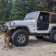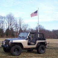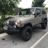
Sab-a-dab-a-doo! The back-country LJ build has officially started

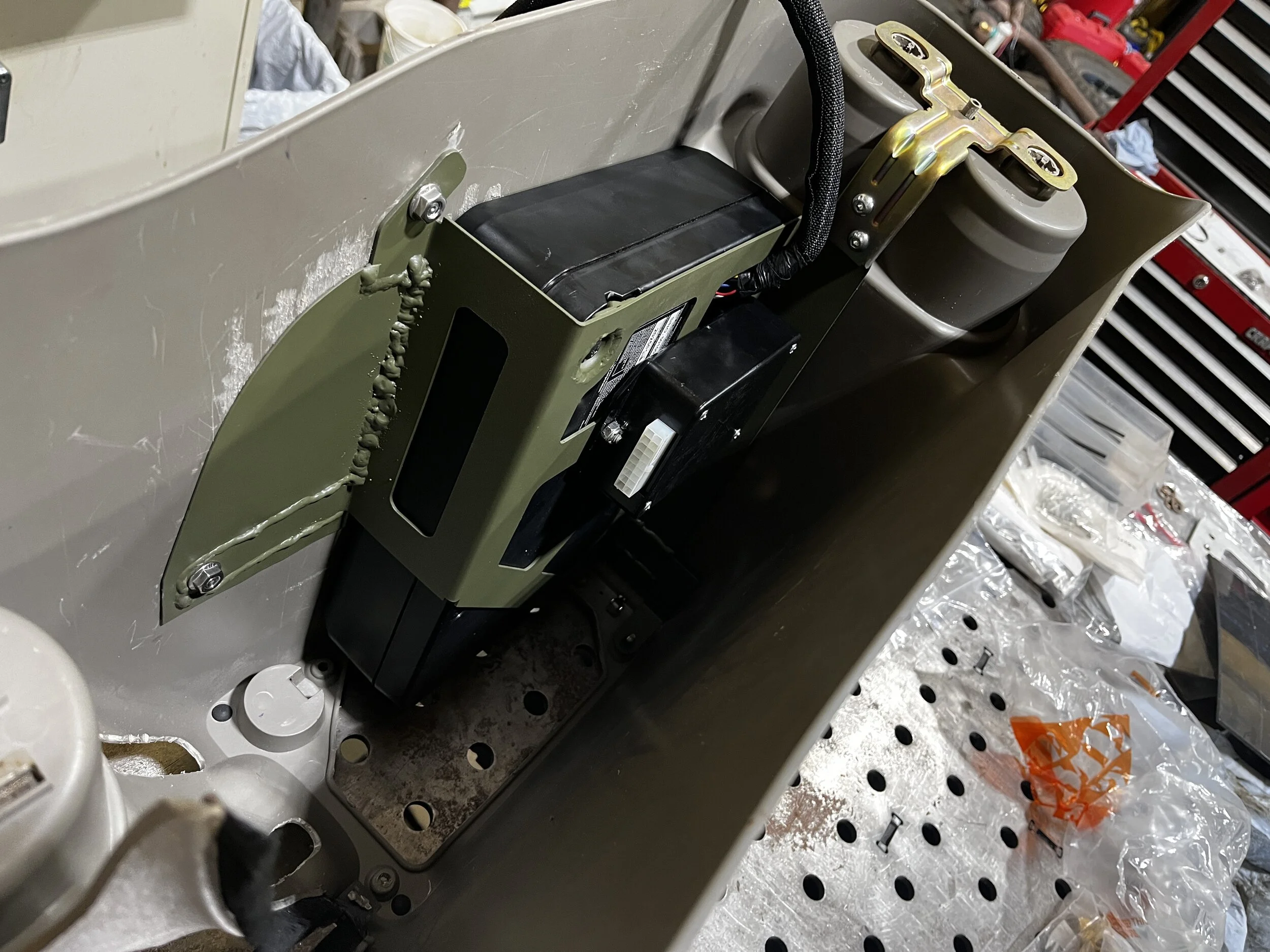
Yesterday morning, I got the subwoofer and step slider control box installed in the console. I apologize for the bad lighting inside the console (I was in a hurry and didn't grab a light), but here's a picture:
IMG_8016.JPG


I was in a hurry because I was needed at my neighbor's shop. He's putting an LS2 into a 1991 Jaguar XJS Coupe to replace the same displacement monster of a V12. The LS2 is so much smaller than that monster V12 (that made less hp and torque!), but the driver-side exhaust manifold, which is out of a Corvette, had to be modified to fit between the steering shaft, motor mount, and rack. It required cutting off the downstream end and grafting on a 90° pipe, along with some custom work with a torch and ball peen hammer.

Today, I have mostly other projects to work on, but I do intend to mount the console. Stay tuned!
 
Last edited:
I continue to have life get in the way of my build, but I made some progress today.

I started the day by installing the modified Rockslide Engineering step sliders. First, I installed the aluminum backers I got from Flux as blanks:
IMG_8039.webp


I installed them using anti-seize because I grew up in the rust belt, and this Jeep will be used occasionally in that environment. I've used anti-seize for decades and dislike it as much as the next guy for how messy it is. When I use it, I take an acid flux brush, cut the bristles short, and paint it on the fasteners to make a minimal mess:
IMG_8040.webp


Next, the modified step sliders get installed, but I realized I had a problem. The trouble with doing a one-off build is that you really don't know what you've missed until final assembly, no matter how many times you install, remove, and reinstall things. As soon as I went to install the step sliders, I realized that the wiring to the motors isn't going to work with the slider backers in place. The solution required a hole through the slider backers and body to pass the wire through:
IMG_8046.webp


After drilling, I removed the backers and re-painted the exposed portions of the backers and the body. Of course, the hole wasn't the only modification needed - the Rockslide Engineering pigtails were too short and needed lengthening:
IMG_8043.webp


And here's a view of how the lengthened pigtails connect to the inside of the sliders:
IMG_8044.webp


And one showing them coming out of the tub after re-installing the backers (noted the crappy touch-up paint on the hole):
IMG_8047.webp


Finally, I installed the sliders:
IMG_8048.webp


And then the slider armor:
IMG_8052.webp


Next up, I have to wire these, but that's for another weekend...
 
With those installed, I decided to install a cabin air filter system. A year ago, I had a friend print @chili_pepper's design for me, since I don't have a 3D printer (yet). I knew that chili_pepper's design involves several pieces that need to be glued together, but I didn't take that into account when selecting a material. At that time, Bambu Labs had just released their PPS-CF material. This material was pretty impressive, so I bought a spool, and that's what we printed it from.

After he printed it, I realized that I needed to find an adhesive compatible with it, so I did some research. PPS is polyphenylene sulfide, and unfortunately, it has very low surface energy, meaning it's very difficult to bond. I contacted an aerospace adhesive company and was quoted $800 per ounce for an adhesive that will bond it, but it also required pre-bond etching with chromic acid (a pretty nasty chemical to dispose of). So, I put this project on the back-burner until I figured out a "Plan B."

Plan B presented itself a few months ago. While working on the rainwater collection system for the homestead, I ended up buying a very nice industrial-grade plastic welder to modify some HDPE tanks, and I realized that I could weld those pieces together:
IMG_8055.JPG


Finished:
IMG_8056.JPG


The last thing needed was a gasket. Some rubber weather stripping from Home Depot did the trick:
IMG_8059.JPG


You can see that I drilled some holes in the bottom of the intake runner. That was to allow water that gets in it to drain out. I have no idea if that will help, but I copied the OEM design, which has a slot there.

Here it is in place (not screwed down, yet):
IMG_8057.JPG


Stay tuned!
 
With those installed, I decided to install a cabin air filter system. A year ago, I had a friend print @chili_pepper's design for me, since I don't have a 3D printer (yet). I knew that chili_pepper's design involves several pieces that need to be glued together, but I didn't take that into account when selecting a material. At that time, Bambu Labs had just released their PPS-CF material. This material was pretty impressive, so I bought a spool, and that's what we printed it from.

After he printed it, I realized that I needed to find an adhesive compatible with it, so I did some research. PPS is polyphenylene sulfide, and unfortunately, it has very low surface energy, meaning it's very difficult to bond. I contacted an aerospace adhesive company and was quoted $800 per ounce for an adhesive that will bond it, but it also required pre-bond etching with chromic acid (a pretty nasty chemical to dispose of). So, I put this project on the back-burner until I figured out a "Plan B."

Plan B presented itself a few months ago. While working on the rainwater collection system for the homestead, I ended up buying a very nice industrial-grade plastic welder to modify some HDPE tanks, and I realized that I could weld those pieces together:
View attachment 641432

Finished:
View attachment 641434

The last thing needed was a gasket. Some rubber weather stripping from Home Depot did the trick:
View attachment 641436

You can see that I drilled some holes in the bottom of the intake runner. That was to allow water that gets in it to drain out. I have no idea if that will help, but I copied the OEM design, which has a slot there.

Here it is in place (not screwed down, yet):
View attachment 641438

Stay tuned!

I've been looking at plastic welders and see a lot of the "heat a staple thing hot and press it in" types. Is that one you have a different concept than those?
 
I've been looking at plastic welders and see a lot of the "heat a staple thing hot and press it in" types. Is that one you have a different concept than those?
Yes. The staples stuff is not what's used for serious plastic-welding, but it does have its place. Backstory - about 25 years ago, and for just a few years, I ran a company that designed and made large, automated plating machines - production lines for putting a finish on parts like faucets and Harley parts. The tanks for these were made from sheets of HDPE that were welded together. Some of the welding equipment was tens of thousands of dollars, but for repairs, smaller, less expensive equipment was available. I couldn't remember the company that made all that equipment. I knew that it was a Swiss company, and Google revealed it: Leister. They are a leader in plastic-welding technology.

The one I bought connects to both compressed air and 120VAC. A heating element heats the air, and that hot air melts the plastic. The control is digital, which is really nice because you can set the temperature at exactly what's need for the type of plastic you're welding (that PPS required a very high temperature - 690°!) There's a tube that you feed the filler rod into (you can see it in the pictures above) and it works similar to TIG welding, but once you get your setup right, the filler rod sticks, and as you draw the iron down the weld, the filler gets pulled through. The hot air melts the two pieces and the filler rod, just like metal welding. It's pretty cool!
 
Last edited:
Yes. The staples stuff is not what's used for serious plastic-welding, but it does have its place. Backstory - about 25 years ago, and for just a few years, I ran a company that designed and made large, automated plating machines - production lines for putting a finish on parts like faucets and Harley parts. The tanks for these were made from sheets of HDPE that were welded together. Some of the welding equipment was tens of thousands of dollars, but for repairs, smaller, less expensive equipment was available. I couldn't remember the company that made all that equipment. I knew that it was a Swiss company, and Google revealed it: Leister. They are a leader in plastic-welding technology.

The one I bought connects to both compressed air and 120VAC. A heating element heats the air, and that hot air melts the plastic. The control is digital, which is really nice because you can set the temperature at exactly what's need for the type of plastic you're welding (that PPS required a very high temperature - 690°!) There's a tube that you feed the filler rod into (you can see it in the pictures above) and it works similar to TIG welding, but once you get your setup right, the filler rod sticks, and as you draw the iron down the weld, the filler gets pulled through. The hot air melts the two pieces and the filler rod, just like metal welding. It's pretty cool!

Interesting that's pretty cool. Sounds useful.. I wonder if it'd be as strong as the melted-in staple for things like interior trim repair in a car. Cool that is it more like literal plastic welding, lol.
 
  • Like
Reactions: Woodrow
You can see that I drilled some holes in the bottom of the intake runner. That was to allow water that gets in it to drain out. I have no idea if that will help, but I copied the OEM design, which has a slot there.

Should not be needed. Unless you flood the cowl area or submerge it, you shouldn't see any water past the filter. The air horn is designed to shed any water that might reach it under normal circumstances. In other words, I feel like you really have to work hard to get water in the system (or your seal at the cowl isn't working). The design was tested a bit... ;)
 
  • Like
Reactions: Woodrow and sab
@chili_pepper just tried downloading the archive from your domain, it gave a big 'ol 404. That host still alive and kicking or do you have the files hosted somewhere else now?
 
Time for through-the-firewall wiring! I've been planning this for a very long time (I bought the connector I'm about to show you over four years ago!) I wanted to make (hopefully) one penetration through the firewall for all wiring, and I wanted to do it with a proper bulkhead connector. The one I settled in is a Weather-Pack 22-terminal bulkhead connector:
IMG_8085.webp


After considering several locations for this over-2" diameter beast, I settled on a location just above the throttle cable. Three holes are required, and the pattern is asymmetric, so I found a drawing of the connector, and it included a hole template:
1758480349077.webp


I printed the template to scale and taped it in place, then center-punched the three hole centers:
IMG_8084.webp


As you can see, in order to get it to sit on the flat surface, I had to place it low enough that the flange will need to be cut through with the hole saw. But before I can get to that, I had to drill the center hole, along with the two screw holes. I started with a small bit:
IMG_8087.webp


And finished them off to 1/4":
IMG_8089.webp


And that's as far as I got this morning. I have a drawer full of hole saws collected over the decades, but this one requires a 2-1/16", which I don't have. I was surprised that it's actually a standard size, though. Amazon will deliver it tomorrow, and I took all week off to get some things done (sadly, not all of it is build work). I'll have to trim the firewall insulation on the inside, which is a project for this afternoon:
IMG_8088.webp


Stay tuned!
 
Amazon came through with the hole saw this morning, so I cut the hole, and the connector fits like a glove:
1758578660691.webp


I removed the connector, hit the bare metal with primer, touch up paint, and clear and will re-install the connector Wednesday. Next up is wiring. Stay tuned!

To see the continuation of this wiring project, skip ahead to Post #961.
 
Last edited:
Today was one of those build days where you realize you have a lot of minor things that are spatially-related, so you have to consider them all in order to do it right. The end result is a major thing that sucks time like a black hole. Summing that sentence up in one word: overwhelming! What started this cascade event was thinking about all the wiring I have to do. In order to come up with a wiring plan, I need all components in their spots.

I started the day working on the inside. Originally, I had bought a boatload of Carling Contura V switches with custom faces and mounted them above the rear view mirror and at the bottom of the center dash (in place of the factory switches). However, that changed when I started this build thread because y'all talked me into the Switch-Pro system instead. I removed the Carling switches and mounted the Switch-Pro switch panel above the rear-view mirror, which required me to relocate the faceplate for my GMRS radio, since it was mounted to the Carling switch panel. Sorry, no pictures of that setup, yet (I need some screws to finish it).

Next, I needed to mount some Carling switches in the factory switch panel because two accessories will still be controlled with conventional switches - the step sliders and the chassis cameras. I started by making a cutting template in Fusion:
Switch Panel Template.webp


Then, I printed it and taped it to the lower dash insert:
IMG_8105.webp


Drew the lines with a blue, fine-point Sharpie, and removed the template:
IMG_8106.webp


I then started the cuts with a ball-end carbide in a rotary tool:
IMG_8107.webp


Then, finished them with a body saw:
IMG_E8108.webp


After some finish work with a file, I popped the switches in:
IMG_E8109.webp


I spent the rest of the day taking measurements for brackets to mount the following in the noted locations:
  1. A bracket to mount the Switch-Pros control box and the ARB CKSA12 locker compressor on the driver fender behind the cruise control driver.
  2. A bracket to mount an ARB breather for the rear differential inside the driver fender well in front of the taillight.
  3. A bracket to mount a manifold and ARB breather for the transmission, transfer case, and front differential inside the new electrical bulkhead connector I just mounted (using the bulkhead connector's mounting bolts).
  4. A bracket to mount a water- and oil-separator for the York compressor and a manifold above the ABS tray on the driver side.
Tomorrow, I'll design the brackets in Fusion and get them on order with SendCutSend. Stay tuned...
 
I got the brackets mentioned in the post above designed this weekend, and I'll be placing a big SendCutSend order this afternoon. Screenshots follow...

Bracket to mount the Switch-Pros control box and the ARB CKSA12 locker compressor on the driver fender behind the cruise control driver:
ARB Compressor-SwitchPro Control Box Mount.png


And since accessing the backside of the ARB compressor mounts is difficult, I designed some "double-flag nuts" (I have to tap the holes myself because SendCutSend said the part is to narrow for them to tap it):
Flag Nut for ARB Compressor Mounting.png


Bracket to mount an ARB breather for the rear differential inside the driver fender well in front of the taillight:
Rear Diff Breather Bracket.png


Bracket to mount a manifold and ARB breather for the transmission, transfer case, and front differential inside the new electrical bulkhead connector I just mounted (using the bulkhead connector's mounting bolts):
Three-way Breather Bracket.png


Bracket to mount a water- and oil-separator for the York compressor and a manifold above the ABS tray on the driver side:
Manifold-Separator Bracket.png


And a bonus bracket. I realized that the Switch-Pros box needs a big fuse at the battery, so I designed this plate to mount it just above the PCM:
SwitchPro Fuse Holder Bracket.png


Designing these to be laser cut makes it very easy to lighten them up, which fits my build methodology quite well. I'd hate to cut these out using the old-school Dykem layout method. I did a lot of that in my college days for SAE student competition. It's mind-blowing how technology has advanced just in my adult life!

I've said it before, and I'll keep saying it. I don't know how SendCutSend does what they do for the prices they charge. They usually give a substantial discount with every additional piece (of the same part), so I often order double quantities to have a spare for a very reasonable cost. They also do more than just laser cutting. They're cutting and bending these out of 304 stainless for me, and three of the parts I was able to get powder-coated matte black to match the factory brackets, like the speedo servo bracket. One part needs welding, so I couldn't have them powder-coat it. The other two were too small for their powder-coating standards, so I'll paint them (only because raw stainless on a vehicle just ain't right to my eye). I've also ordered double of everything, and after shipping, but before sales taxes, it was $140 for single quantities and $200 for double quantities.

I'm sure it's difficult to understand how these work without context, so stay tuned for their installation! Delivery is not until the week after next, so it'll be about two weeks before I can get to it...

Edited to add: I realized that I had to do some welding on two of the other brackets that I was going to order powder-coated, which left just one part powder-coated. Since the powder-coating delayed the order by two days, I decided to forego the powder coating this time. That saved me $50, but will cost me a couple hours of prepping and painting...
 
Last edited:
The double flag nuts that I had SendCutSend make came today. This evening, I used a taper tap with a guided tap handle to tap the 304 stainless:
IMG_8113.webp


And here's how the double flag nuts work with the ARB compressor mount and some M6 flange bolts:
1759540858049.webp


The rest of the brackets won't arrive until Tuesday. Stay tuned!
 
The double flag nuts that I had SendCutSend make came today. This evening, I used a taper tap with a guided tap handle to tap the 304 stainless:
View attachment 646828

And here's how the double flag nuts work with the ARB compressor mount and some M6 flange bolts:
View attachment 646832

The rest of the brackets won't arrive until Tuesday. Stay tuned!

Whenever I see @sab posting pics of his detailed works - my brain projects this MEME and adds this message... I even hear Walken in my head 😂

a821bz.webp
 
  • Like
  • Haha
Reactions: Tob and sab
Ten is five, and two is none? 🤘🏻

I think I've poked a little fun before on this topic - hope you know it's all in jest and respect. You're doing 5D chess and my Jeep 'fab' work is more like the really bigger checkers you play with toddlers...

I've been beyond amazed at how you put this all together - and I learn a lot from your works!
 
How did the SCS do with your bends? I haven't used that yet but I want to - what format did you submit the file to them?
 
I think I've poked a little fun before on this topic - hope you know it's all in jest and respect.
Yes, you have. And, yes I do. It's all in good fun! :)

I've been beyond amazed at how you put this all together - and I learn a lot from your works!
Thanks, once again, for the kind words. The reason I post is to (hopefully) show one man's way of doing things that might help a feller! And, yes, this particular man has quite a clamp collection! :ROFLMAO:

How did the SCS do with your bends? I haven't used that yet but I want to - what format did you submit the file to them?
On the last batch of parts, the jury's still out (they won't be here until Tuesday). However, I've had them bend several parts for me now, and they do incredible work, so I expect these new parts to be awesome, as usual (very precise, and I'm amazed at how well they match the designs.) I use Fusion in sheet metal mode. That mode has a "Create Flat Pattern" function that unbends your part. During that unbending process, the bend distortion is added to the flat pattern, and Fusion puts bend lines in the correct places to account for that bend distortion.

While in the flat pattern, you can export the flat pattern to a dxf file, and that is what you send to SCS. In order for the bend distortion to be properly accounted for, you have to set up a custom material type in the sheet metal mode. That material type has a few properties that depend on the press brake being used to make the parts. SCS has those properties listed for all their bendable material on their website. For instance, I used .074" 304 stainless for the last batch of parts. Here's the web page with that information: https://sendcutsend.com/materials/stainless-steel/#074-bend-specs

And here are the properties you need to set up in Fusion to accurately design a bend:
1759576773308.webp
 
Yes, you have. And, yes I do. It's all in good fun! :)


Thanks, once again, for the kind words. The reason I post is to (hopefully) show one man's way of doing things that might help a feller! And, yes, this particular man has quite a clamp collection! :ROFLMAO:


On the last batch of parts, the jury's still out (they won't be here until Tuesday). However, I've had them bend several parts for me now, and they do incredible work, so I expect these new parts to be awesome, as usual (very precise, and I'm amazed at how well they match the designs.) I use Fusion in sheet metal mode. That mode has a "Create Flat Pattern" function that unbends your part. During that unbending process, the bend distortion is added to the flat pattern, and Fusion puts bend lines in the correct places to account for that bend distortion.

While in the flat pattern, you can export the flat pattern to a dxf file, and that is what you send to SCS. In order for the bend distortion to be properly accounted for, you have to set up a custom material type in the sheet metal mode. That material type has a few properties that depend on the press brake being used to make the parts. SCS has those properties listed for all their bendable material on their website. For instance, I used .074" 304 stainless for the last batch of parts. Here's the web page with that information: https://sendcutsend.com/materials/stainless-steel/#074-bend-specs

And here are the properties you need to set up in Fusion to accurately design a bend:
View attachment 646873

Thanks for the breakdown! I've been playing around with the sheet metal feature in Fusion. It's pretty good - just a little different way to think/plan a part when drawing it. Glad you've had good success with the 'flat' feature with SCS. That was a pretty cool feature to use the first time - tutorials on You-Tube have been very helpful on things to think about - like relieve cuts in corners of bends, etc.

Looking forward to my first use of the bend feature from SCS - as my current brake is vice, MAPP Gas, and hammer...
 
  • Like
Reactions: sab
One of the downsides of the way Fusion works with flat patterns is that the features you create in the flat pattern don’t always render in the bent model. Or at least I haven’t found a way to fix that…
 
  • Like
Reactions: Woodrow