

You are using an out of date browser. It may not display this or other websites correctly.
You should upgrade or use an alternative browser.
You should upgrade or use an alternative browser.

Setting up links for variable height suspension
- Thread starter Wildman
- Start date
Wildman
Over Analyzer Extraordinaire & Attention Whore
Original poster
Staff Member
Supporting Member
The better option is actually the lower height dialed in for highway. Offroad, it would be rare where the offset front axle is much of an issue. Bigger benefit is better handling and lower wind resistance on the highway.
Since it is mainly a trail rig and is only driven on the road to get to the trail from the campsite would this still be your suggestion?
The mid arm doesn't really care that much. Get about 4.5" of lift average and the geometry will work plus the rear axle won't be off center at any height. The mid arm front will have less bind when the trackbar pulls the axle over so that is a non issue as well. BTW- I doubt many on here would recognize Larry from the back of his head.
I guess what I am asking is will the frame brackets allow me to move them from the spots for a stock WB?
Set my ride height at 4.5" (Do I measure the amount of shock shaft showing to get this?) and it will work?
With my HP44 and CRD 60 what will I have to do for mounting the upper links? Next question is that I drilled my lower links for the Nth Degree kit. Is that going to screw anything up? I saw astip2 asking about mounting on a HP44. I have the RE front bracket kit that has a truss over the front diff. It came with a tie-in plate to bolt to the cover but I could never get it to fit. My front axle has the right upper link so from what you have said that get cut it off and the tube truss will work? My axle tubes are 2 3/4". The CRD has the 4 holes tapped in top somewhat like the RJ60's I've seen.
He was a friend from up here in the PNW who moved to Las Vegas and opened a 4x4 shop. Also was involved with Crawl magazine. Still might be but I don't know. I know him and Blaine know each other and Blaine has worked on his LJ but I don't know that story.Who's Larry?
Last edited:

Wildman
Over Analyzer Extraordinaire & Attention Whore
Original poster
Staff Member
Supporting Member
Wildman
Over Analyzer Extraordinaire & Attention Whore
Original poster
Staff Member
Supporting Member
Will this truss work or would I have to remove it and install the Savvy truss?
View attachment 85743
Is there any type of third leg that connects to the center section?
Wildman
Over Analyzer Extraordinaire & Attention Whore
Original poster
Staff Member
Supporting Member
Here is the finished axle. No it doesn't.Is there any type of third leg that connects to the center section?

Will this truss work or would I have to remove it and install the Savvy truss?
That truss will make your Jeep catch on fire and cause you to be forever-unpopular with the ladies.

Wildman
Over Analyzer Extraordinaire & Attention Whore
Original poster
Staff Member
Supporting Member


The bridge may be sufficient for a 4 link (maybe?). But a 3 link would need a plate that reaches down to the top few diff cover bolts for some added strength, similar to what Savvy does on the rear.
Wildman
Over Analyzer Extraordinaire & Attention Whore
Original poster
Staff Member
Supporting Member
What is the reason for the truss that goes over the axle tube? Like I said I have/had the tie in piece that came with the bracket kit but it didn't want to line up so I never installed it. Wonder what it would take to make something? It was the same thickness as the bridge truss so it isn't something I could bend. All this would have to get worked out.
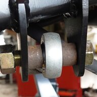
The tie in reinforcement stops the platform deflection. It is unlikely the forces will be able to deflect the bridge laterally due to the double angles on each side up off the tubes. What will or can happen since it can't easily go those directions is the front lower edge will deflect up or down since it is unsupported and unbraced. It is just a flat piece of steel and will move up or down at the front edge fairly easily. The reason there is a tie in brace is so the cover can be removed otherwise there would just be a bent flange down along the front edge.The bridge may be sufficient for a 4 link (maybe?). But a 3 link would need a plate that reaches down to the top few diff cover bolts for some added strength, similar to what Savvy does on the rear.
Care must also be taken to ensure that the bolts that go into the casting are full depth in holes that have been cleaned out with a bottoming tap to remove any built up RTV or thread locker. The iron is fairly soft comparatively and the bolt needs all the thread engagement it can get to provide the clamping force to hold the lower end of the brace immobile.
Wildman
Over Analyzer Extraordinaire & Attention Whore
Original poster
Staff Member
Supporting Member
I'll have to look and see if I can find the tie in plate that came with the kit. If I remember right when Larry and I were installing it the angle of the tie in plate wasn't lining up and neither of us could figure out how to mount it.
Does the brace going down the axle tube just help strengthen the bridge truss?
Does the brace going down the axle tube just help strengthen the bridge truss?
Last edited:
What is the reason for the truss that goes over the axle tube?
Be more specific, please. Use pictures and/or drawings, preferably made with crayon.
I was wondering if this thread was copied and pasted to/from pirate. Confirmed.
Thought I was going crazy.
Thought I was going crazy.
Wildman
Over Analyzer Extraordinaire & Attention Whore
Original poster
Staff Member
Supporting Member
Be more specific, please. Use pictures and/or drawings, preferably made with crayon.
I can't draw and I gave all my crayons to the Marines.
I was wondering if this thread was copied and pasted to/from pirate. Confirmed.
Thought I was going crazy.
It was suggested that I might get more advice there. And it wasn't copied and pasted.
I can't draw and I gave all my crayons to the Marines.
Then find a picture that illustrates the part you're asking about; I'm genuinely unsure about what you're trying to figure out, so without more description or an image there's only so much that can be explained. Thus far, all I have to work on is "truss that goes over the axle tube" and that's pretty vague.
Wildman
Over Analyzer Extraordinaire & Attention Whore
Original poster
Staff Member
Supporting Member
Then find a picture that illustrates the part you're asking about; I'm genuinely unsure about what you're trying to figure out, so without more description or an image there's only so much that can be explained. Thus far, all I have to work on is "truss that goes over the axle tube" and that's pretty vague.
The axle tube going from the center section to the right outer "C".
Oh, that? That's just more of the truss assembly; with that piece present, the bridge has to work against the entire axle tube and the truss structure itself if it wants to move.
While that piece does in fact do what you state, it was designed more as a fluff piece to quell the shouting I see for trusses and why you are deficient if you don't run one. So, I made one that works as a stiffener for the long side tube that also reinforces the bridge (unnecessarily). The bridge is and can be stand-alone as designed without the stiffener since it picks up the cut off cast mount for the upper control arm bushing. It is also flanged down in the back and front where it can be and the missing flange over the diff is well compensated for by the mechanical connection to the cut off mount. The bridge also welds fully across the top of the spring mount.Oh, that? That's just more of the truss assembly; with that piece present, the bridge has to work against the entire axle tube and the truss structure itself if it wants to move.

Similar threads

- Replies
- 17
- Views
- 2,641


- Replies
- 17
- Views
- 6,970


- Replies
- 33
- Views
- 3,733

- Replies
- 25
- Views
- 1,990
