Nashville TJ's Build - Continued

This thing puts so much heat into the air stream that ARB recommends running it with a heat synch. They sell one of course, but it is small - and kind of ugly.

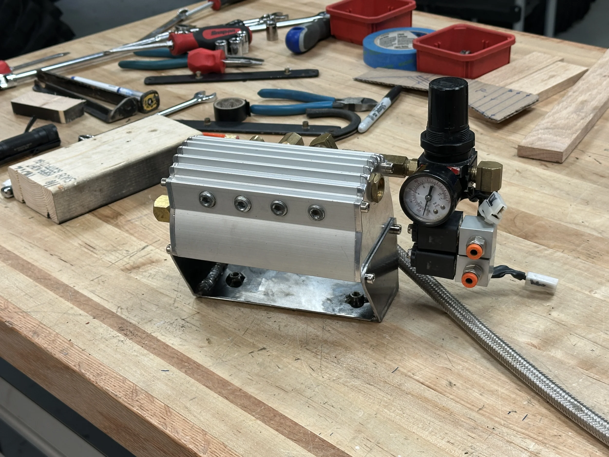
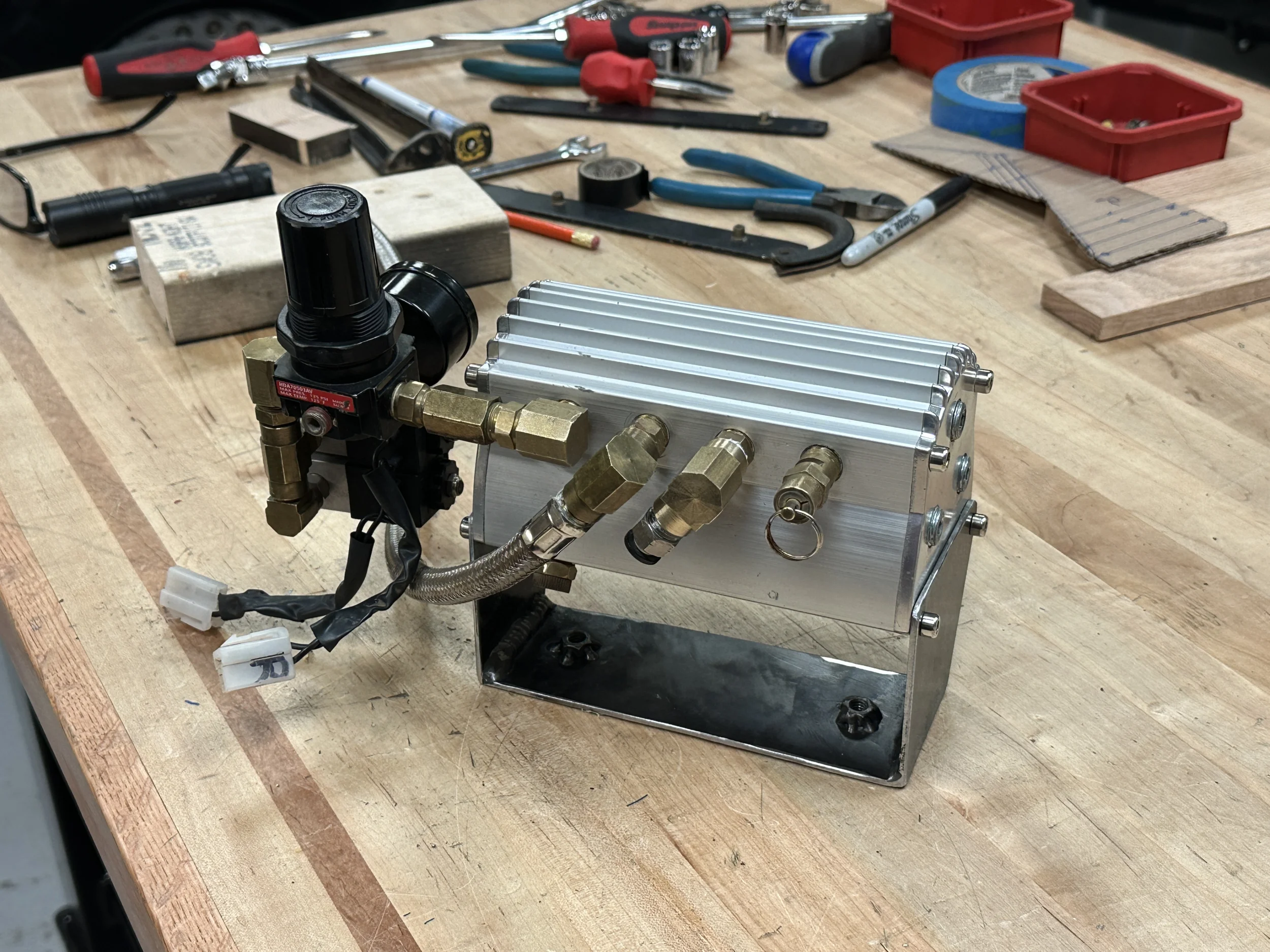
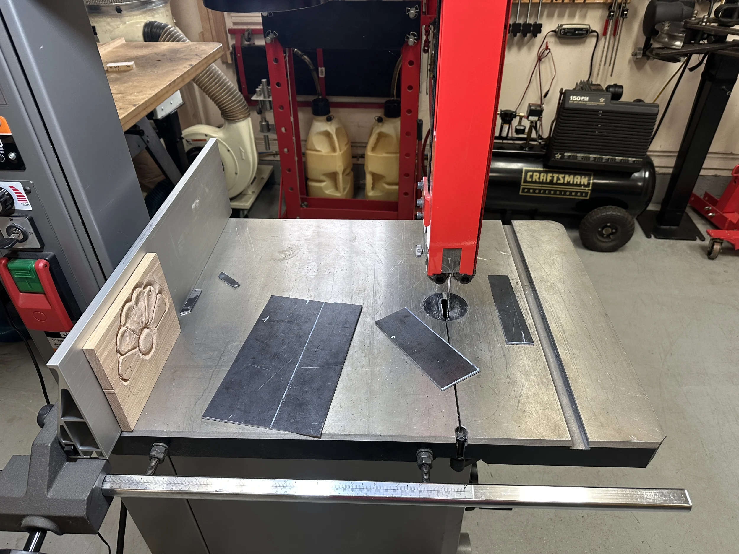
The old Viar had a heat synch / manifold as part of the pump assembly. It is larger than the ARB version, has 12 ports, and will fit the space nicely. It just needs a mount - so I went to work.

Always a good day when the big band saw sucks up a little 220...
IMG_1716.webp


This is the mount, as well as my beginning to figure out the plumbing (that turned out to be quite the puzzle :oops:):

IMG_1726.webp


IMG_1727.webp


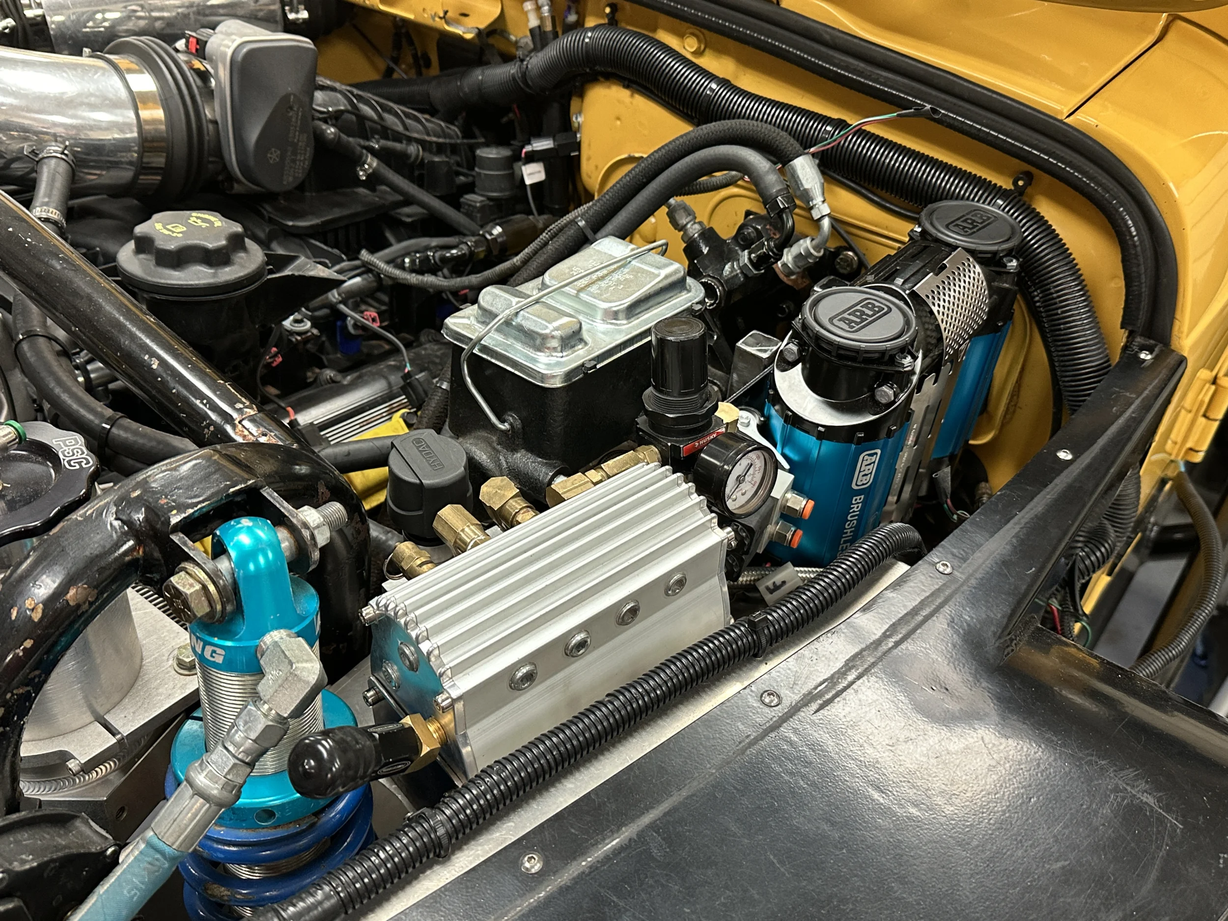
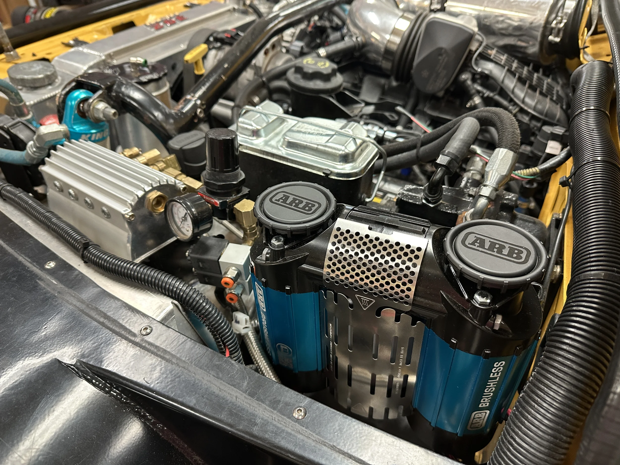
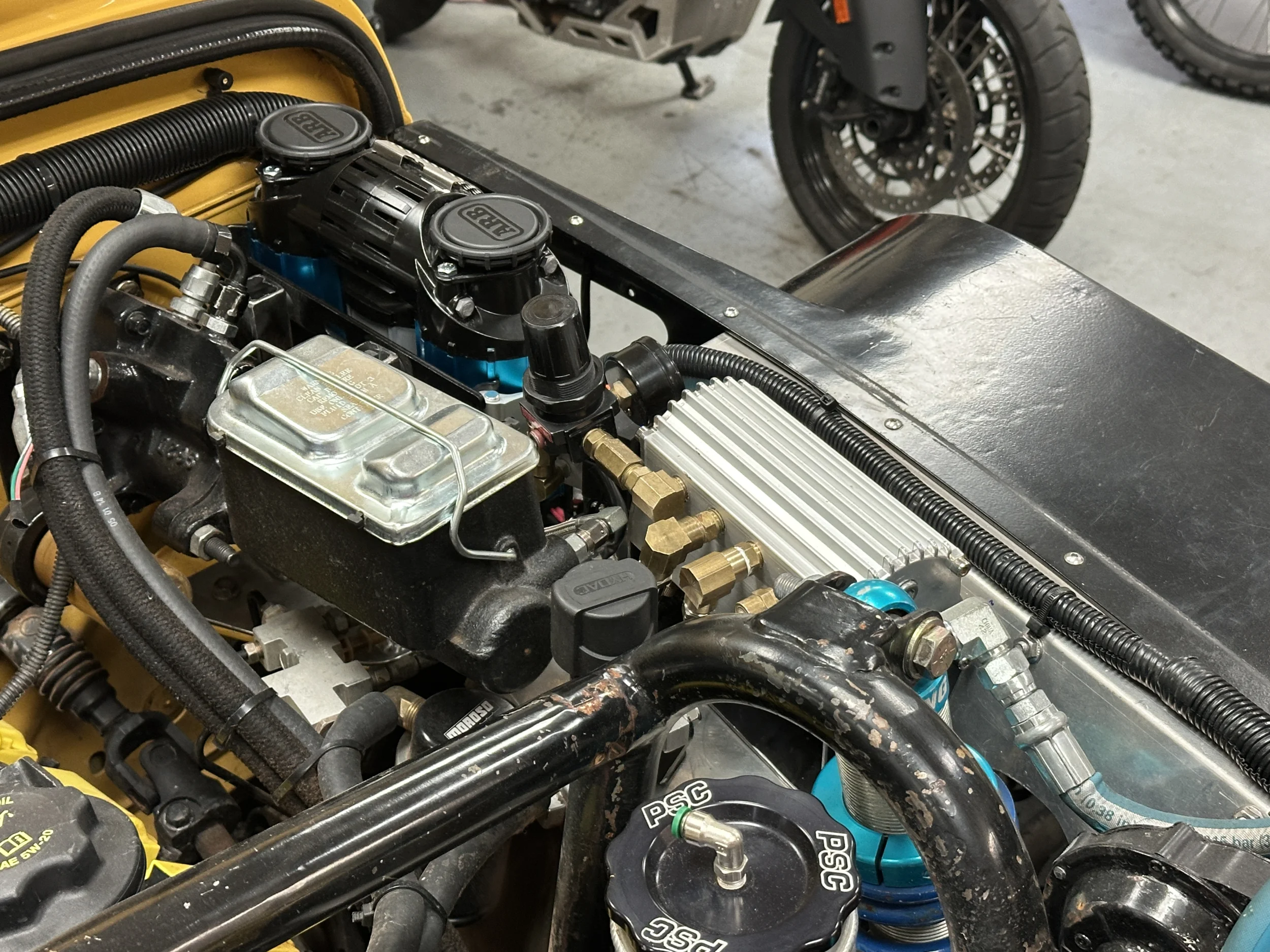
And here is everything installed:

IMG_1738.webp


IMG_1736.webp


IMG_1734.webp


Man, this was quite the project. I've certainly simplified and summarized the process, but this was nearly two full days in the shop. But, I'm stoked with how well it turned out.

Next up - wiring. Given that I already have an ARB locker setup, that should be a piece of cake - although I will need to tear into the ARB wiring harness and make a few changes. But, given that there is no need for a relay setup with the brushless motors, it should be quite a bit simpler.
 
Last edited:
Well, if you're going to install a Hemi and reduce the brake booster size — obviously you have perfect install spot. You Hemi guys — always creating extra engine bay volume on TJ installs.....


——

I kid — I plan to use the same location but the OEM TJ booster has me trying to run mine up at an angle against the inner & outer fender.

Very clean install spot and design! As always.

Thanks FF!

Yeah, the hydroboost certainly saves a bunch of space by eliminating that booster. And as a side benefit - it makes the brakes quite a bit stronger - who'd a' thought?

:)
 
This thing puts so much heat into the air stream that ARB recommends running it with a heat synch. They sell one of course, but it is small - and kind of ugly.

The old Viar had a heat synch / manifold as part of the pump assembly. It is larger than the ARB version, has 12 ports, and will fit the space nicely. I just needs a mount - so I went to work.

Always a good day when the big bad saw sucks up a little 220...

View attachment 699705

This is the mount, as well as my beginning to figure out the plumbing (that turned out to be quite the puzzle :oops:):

View attachment 699706


View attachment 699707

And here is everything installed:

View attachment 699708

View attachment 699709

View attachment 699710

Man, this was quite the project. I've certainly simplified and summarized the process, but this was nearly two full days in the shop. But, I'm stoked with how well it turned out.

Next up - wiring. Given that I already have an ARB locker setup, that should be a piece of cake - although I will need to tear into the ARB wiring harness and make a few changes. But, given that there is no need for a relay setup with the brushless motors, it should be quite a bit simpler.

Curious what all you're running off that manifold? I can't keep all the builds straight - are you running ARB lockers?

I'm 50/50 to run a manifold on mine (not brushless) since I just plan to use it for tire inflation. So I like to ask on installs before I pull the trigger on mounting & wiring/hosing mine.
 
  • Like
Reactions: reddvltj
Curious what all you're running off that manifold? I can't keep all the builds straight - are you running ARB lockers?

I'm 50/50 to run a manifold on mine (not brushless) since I just plan to use it for tire inflation. So I like to ask on installs before I pull the trigger on mounting & wiring/hosing mine.

Yes, ARB lockers front and rear - hence the pressure regulator and actuators. The other connections are for the air input (obviously...), tire fill connector, safety blow-off valve, and an air gauge in the cab.

ARB says you can run this without the heat synch, but I'm not kidding here: they say in that case you need to run something like two meters of steel heat resistant line before it connects to anything. As I said, this thing puts out some heat.
 
I knocked a few more items off of the brushless project task list this week. First up, I cut a hole in the heat shield to allow the feed hose from the pump to pass through. This hose gets crazy hot, and care has to be taken to make sure it is routed away from anything it may damage - especially wiring. I spent a good bit of time coming up with the best path to the manifold.

IMG_1831.webp


IMG_1832.webp


And speaking of the feed hose, I picked up a new one from Viair (yes, Viair parts on an ARB pump :rolleyes:). I needed a 24" hose for my selected route, and all mine are 18". The one I picked up also has a build in heat/abrasion sleeve, and the necessary check valve:

IMG_1852.webp


IMG_1833.webp


Cutting that hole was the last piece of fab work for the project.
 
Next up: wiring.

With the brushless design, the upside is that the wiring is a bit simpler as it eliminates the need for a relay to power the pump. The downside is that this thing draws 90 amps! So, the wiring requires a bit of thought.

I dropped a fuse panel directly connected to the battery via a short 6-gauge connection onto the inner fender. You are reading this correctly: those are 60 amp fuses powering separate circuits for each of the motors. From the fuse block, 10-gauge wire to the motors.

IMG_1745.webp


IMG_1853.webp


The stock wiring harness from ARB also included all the necessary wire and connectors for the on-off and locker control switches, all of which are already in place on the rig. So I pulled the ARB harness apart and stripped out everything I did not need. In addition to the power feeds, I only left the speed controller, the trigger wire, and the pressure switch wiring.

I then grafted all of that into my existing harness.

IMG_1845.webp


All that is left is to seal up all of the plumbing connections, and get everything installed.

Almost there. :cool:
 
Next up: wiring.

With the brushless design, the upside is that the wiring is a bit simpler as it eliminates the need for a relay to power the pump. The downside is that this thing draws 90 amps! So, the wiring requires a bit of thought.

I dropped a fuse panel directly connected to the battery via a short 6-gauge connection onto the inner fender. You are reading this correctly: those are 60 amp fuses powering separate circuits for each of the motors. From the fuse block, 10-gauge wire to the motors.

View attachment 700676

View attachment 700677

The stock wiring harness from ARB also included all the necessary wire and connectors for the on-off and locker control switches, all of which are already in place on the rig. So I pulled the ARB harness apart and stripped out everything I did not need. In addition to the power feeds, I only left the speed controller, the trigger wire, and the pressure switch wiring.

I then grafted all of that into my existing harness.

View attachment 700679

All that is left is to seal up all of the plumbing connections, and get everything installed.

Almost there. :cool:

I'd run #2 for the single run, and #6 for the split load.
 
  • Like
Reactions: pc1p
I'd run #2 for the single run, and #6 for the split load.

ARB's wiring harness came with the 10 gauge for the dual run - about 6 feet of it. And something just a bit larger for the single run - which I replaced with the much larger 6 gauge. I looked at the specs for the current and the standard wire recommendations are larger than what ARB provides - but I assume they have had no issues with their setup.

But if I post up a pic in the next few weeks of the rig having burst into flames - we will know what happened... :oops:
 
ARB's wiring harness came with the 10 gauge for the dual run - about 6 feet of it. And something just a bit larger for the single run - which I replaced with the much larger 6 gauge. I looked at the specs for the current and the standard recommendation for that current are larger than what ARB provides - but I assume they have had no issues with their setup.

But if I post up a pic in the next few weeks of the rig having burst into flames - we will know what happened... :oops:

Its not gonna burn up - but voltage drop isn't your friend in a DC system like this. I always oversize.
 
Its not gonna burn up - but voltage drop isn't your friend in a DC system like this. I always oversize.

A good thing about this brushless setup is that the speed controller monitors itself for voltage, and will shut down the motors one at a time if the voltage drops below the ARB spec. So I'll at least get a hint if the wiring is not up to the task. I know this works as it would not run, and gave an audible code, when I tried to test it with a standalone 12-volt battery.

By the way Big-Z, are you just discovering this thread? This is like the three thousandth fab project I've done on the thread, and I'm glad you are following and commenting. I appreciate your electrical insight.
 
I disassembled everything, and then put it all back together with Loctite 545.

View attachment 700732

And then installed for the last time. A quick bath of soapy water for a leak check, and everything looks good.

View attachment 700733

Just perfect Jeff. Not just the new brushless pump, but the post Sand Hollow repairs and upgrades, too. If I make it 20 yrs in with my build, I hope it is at (or even near) the point yours is👍

Early on in my presence on this forum, I recall saying that your Jeep is one of my favorites on here. I stand by that.
 
IMG_1845.webp


Luckily all the 'TJ Fest' trips are out west so this wiring solution won't be at risk for getting caught on an East Coast tree....

Hinting Celebrity Family Feud GIF by ABC Network


Hint Hint...

;) (Jeff - you aren't the planner of the Fest but I thought a fun moment to bring this up..... — sorry, been having a few 'fun' moments on your build)
—-

Great looking install Jeff! Coming together nicely.


I like your little paint booth. I overthink mine and the quality looks crappier than yours recently when I'm painting outside on my end...
 
While hanging around the shop waiting to see if the new pump setup holds pressure over the long term (it does!) I did a quick (and related) sewing project.

I carry a coiled air hose in the rig. Those of you who have used and try to store these things know that they can be a bit unruly. So, I threw together a canvas sleeve to get back a little bit of the "ruly." 🙂

IMG_1866.webp


The hose slides in and out easily, and the sleeve keeps everything in a smaller space:

IMG_1869.webp
 
I'm going to need to go back and study what you've done here. Ive mounted the compressor and just had lockers installed. Nothing is plumbed or wired yet. I've got other issues that have decided they need attention, ( powerstroke oil cooler)
 
  • Like
Reactions: Irun and reddvltj
Now that everything is in and running, given this thing’s 90 amp draw I wanted to double check the wiring. First up, I checked the voltage drop across the ground. With the compressor in full draw, I was seeing -.12 volts, which I think is good, and validates the quality of my ground.

IMG_1870.webp


I also tried to test the voltage drop across the hot side, but was getting 0. The display was changing each time I made the connection - so I was getting a reading - but this can’t be right. I would certainly expect some small drop.

I’ll have to play with it some more, but any suggestions?

I did repeat my fill test from 10-25 psi on the fodeez, and at exactly 1:25 it matched my testing prior to the install exactly - so that was good.
 
Now that everything is in and running, given this thing’s 90 amp draw I wanted to double check the wiring. First up, I checked the voltage drop across the ground. With the compressor in full draw, I was seeing -.12 volts, which I think is good, and validates the quality of my ground.

View attachment 700989

I also tried to test the voltage drop across the hot side, but was getting 0. The display was changing each time I made the connection - so I was getting a reading - but this can’t be right. I would certainly expect some small drop.

I’ll have to play with it some more, but any suggestions?

I did repeat my fill test from 10-25 psi on the fodeez, and at exactly 1:25 it matched my testing prior to the install exactly - so that was good.

Change your meter off auto ranging and lock in the range, mv would be fine unless you messed something up bad, which I don’t think you did.